6
Safety Precautions
UL Cautions, Warnings and Instructions
The warnings and instructions in this section summarizes the procedures necessary to ensure an inverter installation
complies with Underwriters Laboratories guidelines.
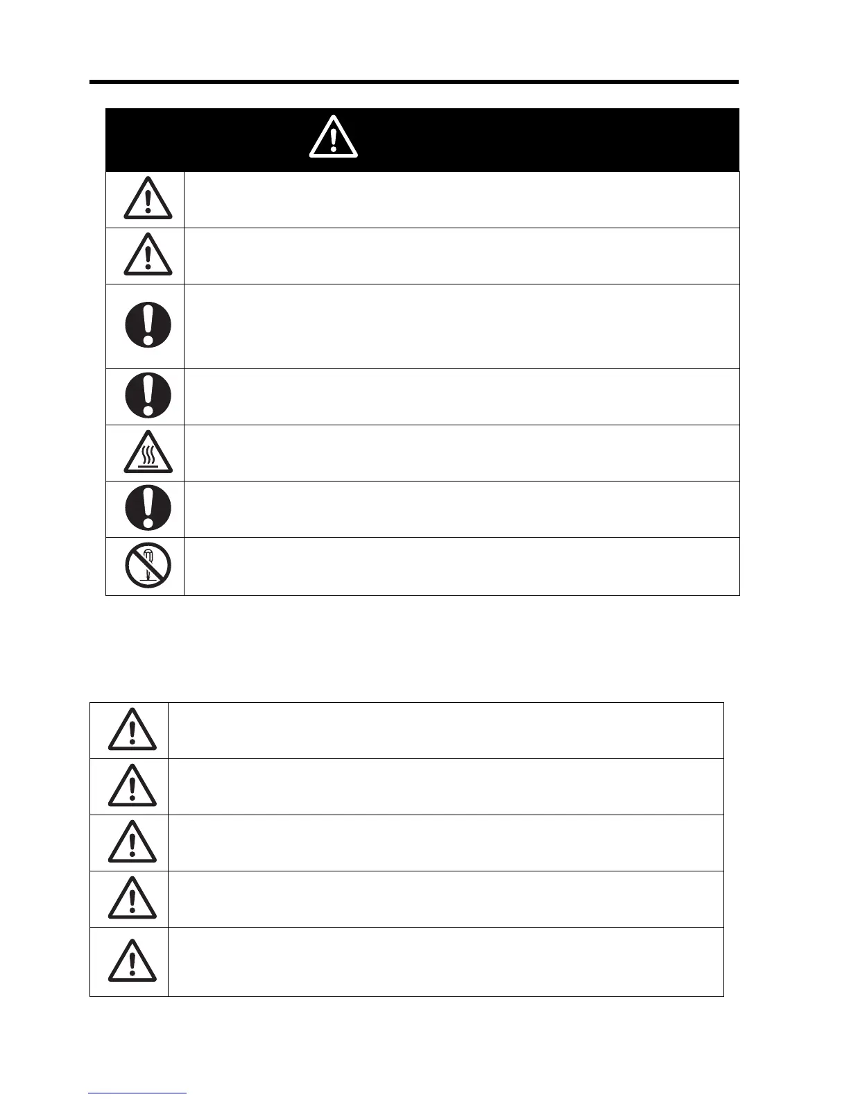
Do not connect resistors to the terminals (+1, P/+2, N/-) directly.
Doing so might result in a small-scale fire, heat generation or damage to the unit.
Install a stop motion device to ensure safety. Not doing so might result in a minor injury. (A holding
brake is not a stop motion device designed to ensure safety.)
Be sure to use a specified type of braking resistor/regenerative braking unit. In case of a braking
resistor, install a thermal relay that monitors the temperature of the resistor. Not doing so might
result in a moderate burn due to the heat generated in the braking resistor/regenerative braking
unit. Configure a sequence that enables the Inverter power to turn off when unusual overheating is
detected in the braking resistor/regenerative braking unit.
The Inverter has high voltage parts inside which, if short-circuited, might cause damage to itself or
other property. Place covers on the openings or take other precautions to make sure that no metal
objects such as cutting bits or lead wire scraps go inside when installing and wiring.
Do not touch the Inverter fins, braking resistors and the motor, which become too hot during the
power supply and for some time after the power shutoff. Doing so may result in a burn.
Take safety precautions such as setting up a molded-case circuit breaker (MCCB) that matches
the Inverter capacity on the power supply side. Not doing so might result in damage to property due
to the short circuit of the load.
Do not dismantle, repair or modify the product.
Doing so may result in an injury.
CAUTION
“USE 60/75×C Cu wire only” or equivalent. For models JX-AB007, -AB015, -AB022, -A2015,
-A2022, -A2037, -A2055, -A2075
“USE 75°C Cu wire only” or equivalent. For models JX-AB002, -AB004, -A2002, -A2004, -A2007,
-A4022, -A4037, -A4055, -A4075
“Use 60°C Cu wire only” or equivalent. For models JX-A4004, -A4007 and -A4015
“Open Type Equipment”
“Suitable for use on a circuit capable of delivering not more than 100k rms symmetrical amperes,
240V maximum when protected by Class CC, G, J or R fuses or circuit having an interrupting rating
not less than 100,000 rms symmetrical amperes, 240 volts maximum”. For the single and three
phases 200V models.