4-44
4-2 Function Mode
4
Functions
Allocate 52 (RDY) to the desired multi-function input
•Inputting this signal shortens the time between the RUN command input and the start of actual
operation. In normal status, this is approx. 20 ms. Shortened time through this function varies
depending on timing.
<Group C: Multi-function Terminal Function>
The JX has five input terminals [1], [2], [3], [4] and [5]; one open collector output terminal [11]; two
relay output terminals [AL2] and [AL1] (SPDT contact); and one analog output terminal [AM].
Multi-function Input Selection
The five input terminals [1], [2], [3], [4] and [5] act as multi-function input terminals, whose functions
can be changed through reallocation. 31 functions are available for allocation.
You can switch the input logic between Sink and Source, and the contact specifications between
NO and NC. (NO [normally open] is allocated by factory default.)
•The terminal with reset allocated is fixed to NO.
•Multi-function input terminal 3 is also used for emergency shutoff input. With DIP switch S8 on the
control PCB turned on, emergency shutoff input works. If a signal is input to terminal 3, the output
is shut off and an error occurs, not through software but only through hardware.
The same two functions cannot be allocated to the multi-function input terminals. If you attempt to
allocate the same two functions to the terminals by mistake, the terminal where you allocated the
function last takes precedence. The previous data is set to "255", and the terminal function is
disabled.
•PTC can be allocated only to input terminal [5].
•Parameter No. C001 to C005 correspond to input terminals [1] to [5] respectively.
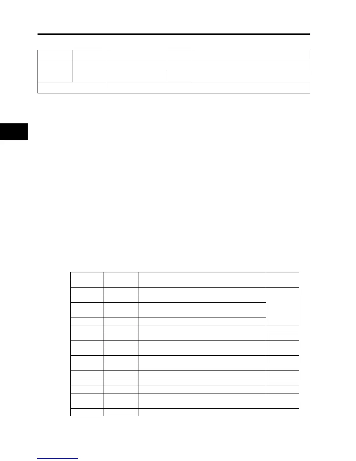
This table presents all the multi-function inputs functions available
Data Symbol Function name Status Description
52 RDY Ready function
ON The Inverter is ready.
OFF Normal stop status
Related parameters
C001 to C005
Data Description Reference item Page
00 FW Forward command -
01 RV Reverse command -
02 CF1 Multi-step speed setting binary 1
4-12
03 CF2 Multi-step speed setting binary 2
04 CF3 Multi-step speed setting binary 3
05 CF4 Multi-step speed setting binary 4
06 JG Jogging 4-14
07 DB External DC injection braking 4-17
08 SET 2nd control selection 4-47
09 2CH 2-step acceleration/deceleration 4-27
11 FRS Free-run stop 4-41
12 EXT External trip 4-49
13 USP Power recovery restart prevention 4-50
15 SFT Soft lock 4-35
16 AT analog input switching 4-10
18 RS Reset 4-50
19 PTC Thermistor input 4-51
20 STA 3-wire start 4-52