2-23
2-2 Wiring
2
Design
*4. For the external analog input indicated above, use a shielded wire for connection and connect the shielded
part to terminal L for stable operation.
*5. Below are the contact specifications of the relay output.
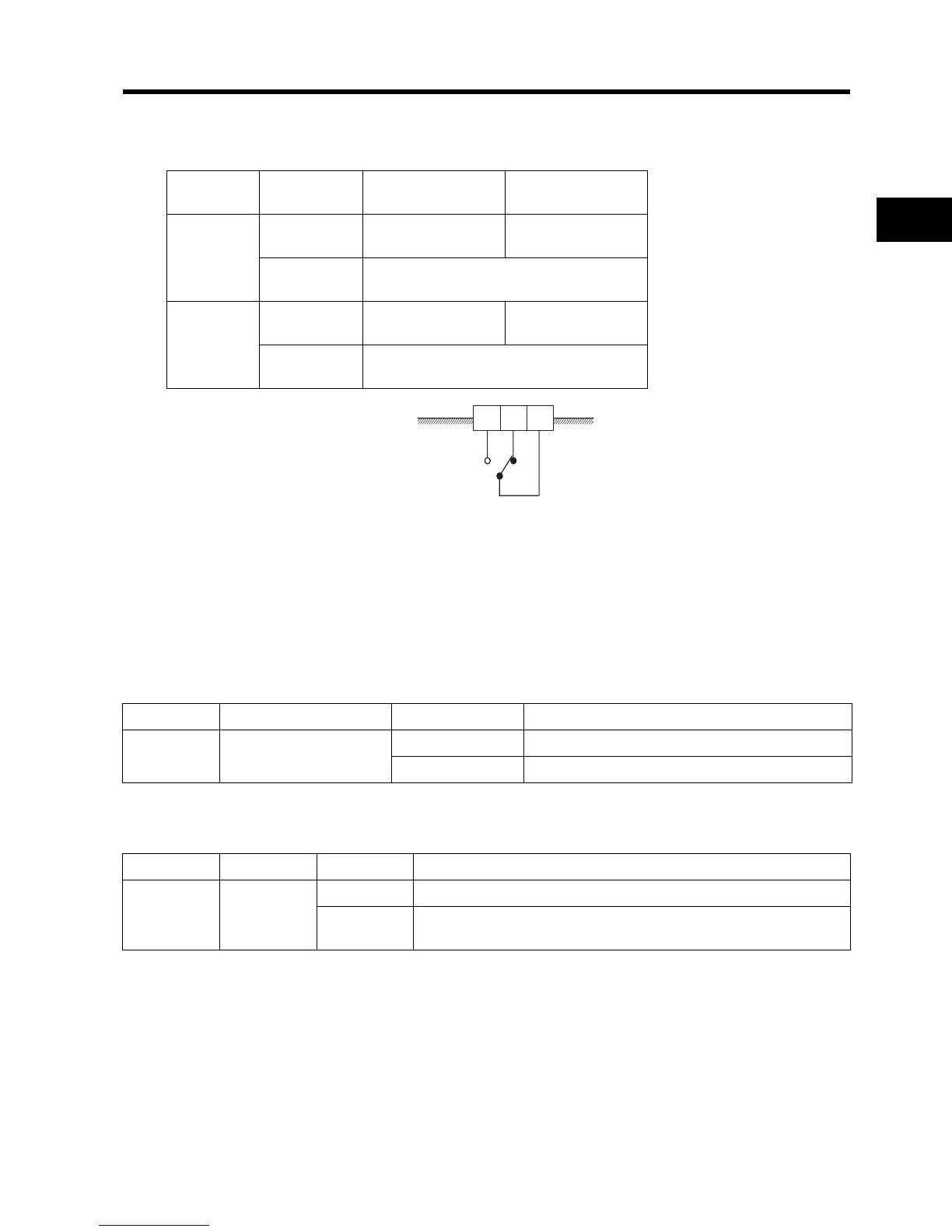
*6.
By factory default, the relay output (AL2, AL1) contact selection (C036) is set at NC contact between AL2-AL0, and
NO contact between AL1-AL0.
Mode Selector
RS-485 Communication/Operator Selector (S7)
Select the mode according to the option connected to the communications connector.
When using the 3G3AX-OP01 supplied with the Inverter, it is available regardless of the switch
condition.
Emergency shutoff selector (S8)
Use this selector to enable the emergency shutoff input function.
*1 The multi-function input terminal 3 is switched to a terminal for emergency shutoff input, and the allocation of
other multi-function input terminals is also changed automatically. Do not set to ON immoderately. For details,
refer to "Emergency Shutoff Input Function" (page 4-46).
Output
terminal
Contact
capacity
Resistance load Inductive load
AL2-AL0
Max.
250 V AC 2.5 A
30V DC 3 A
250 V AC 0.2 A
30 V DC 0.7 A
Min.
100 V AC 10 mA
5 V DC 100 mA
AL1-AL0
Max.
250 V AC 1 A
30 V DC 1 A
250 V AC 0.2 A
30 V DC 0.2 A
Min.
100 V AC 10 mA
5 V DC 100 mA
Inside the Inverter
(Factory default)
AL1
AL2
AL0
Symbol Name Status Description
S7
RS-485 communication/
operator selector
485 RS485 ModBus communication
OPE [Default] Digital Operator (Option: 3G3AX-OP1)
Symbol Name Status Description
S8
Emergency
shutoff
selector
ON Emergency shutoff input enabled
*1
OFF
[Default]
Normal