4-5
4-1 Monitor Mode
4
Functions
Fault Monitors 1[d081], 2[d082], 3[d083]
Displays the details of the last three trips.
The most recent trip is displayed on trip monitor 1.
(Display)
•Factor (E01 to E60)
*1
•Output frequency at the time of tripping (Hz)
•Output current at the time of tripping (A)
•Internal DC voltage at the time of tripping (V)
•Total RUN time before the trip (hr)
•Total power supply time before the trip (hr)
*1. Refer to "Error Code List" (page 5-2) and "Trip Monitor Display" (page 5-5).
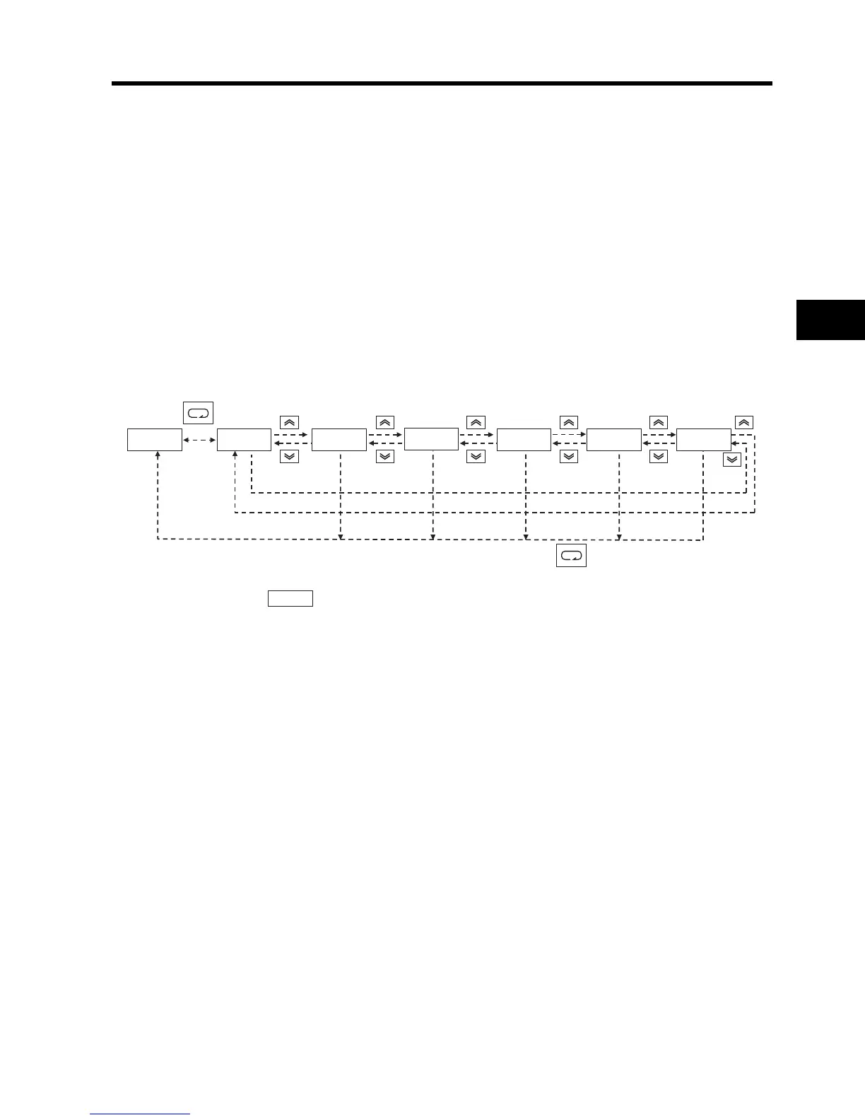
(Trip Monitor Display Sequence)
*2. Displays if there has been no trip.
DC Voltage Monitor [d102]
Displays the main circuit DC voltage of the Inverter.
(Display)
0.0 to 999.9 : Displays in increments of 0.1 V.
Electronic Thermal Monitor [d104]
Displays the count integration value of the electronic thermal. An overload trip occurs if it reaches
100% (E05).
(Display)
0.0 to 100.0 : Displays in increments of 0.1%.
(1)Trip factor
*2
(2)Trip frequency (3)Trip current (4)Trip P-N voltage (5)Total RUN time (6)Power ON time
d081 e 07 60.0 4.0 398. 15. 18.
_k_k_k_