1. Grasp the Base Module chassis by the sides and remove it from the shipping
carton.
2. If there are no Expansion Modules for this library, install the floor in the Base
Module.
See Install the Floor in the Bottom Expansion Module.
3. Mount the Base Module.
Install the Base Module CRUs and Expansion Modules
Reinstall the function components removed from the defective Base Module and install
any Expansion Module.
1. Reinstall the Base Module components.
• Replace the Robot Module
• Replace the Drive Tray
• Install the Drive Slot Cover
• Replace the Power Supply
• Install a Power Supply Slot Cover
• Replace the Front Control Panel
2. Reinstall the Expansion Modules. See Replace the Expansion FRU Chassis. Make
sure to install the floor in the bottom module.
3. Re-cable the Expansion Modules. Connect the specific Base Module port to the
controller card port of the associated Expansion Module. See Cable the Expansion
Modules for details.
Reinstall Magazines and Dress the Cables
Reinstall the cartridge magazines into all modules and dress any cabling.
1. Install cartridge magazines in all modules.
See Replace the Cartridge Magazines.
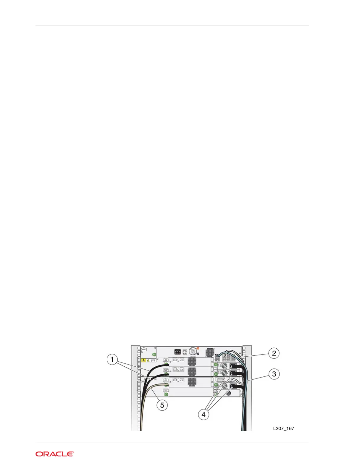
2. Align and dress the cables. Secure the cables in the hook and loop straps, if
applicable.
Figure 10-8 Cable Attachment
Chapter 10
Base Module Chassis Removal and Replacement (FRU)
10-24