Understanding PCIe Root Complex Connections
154 SPARC T5-4 Server Service Manual • July 2016
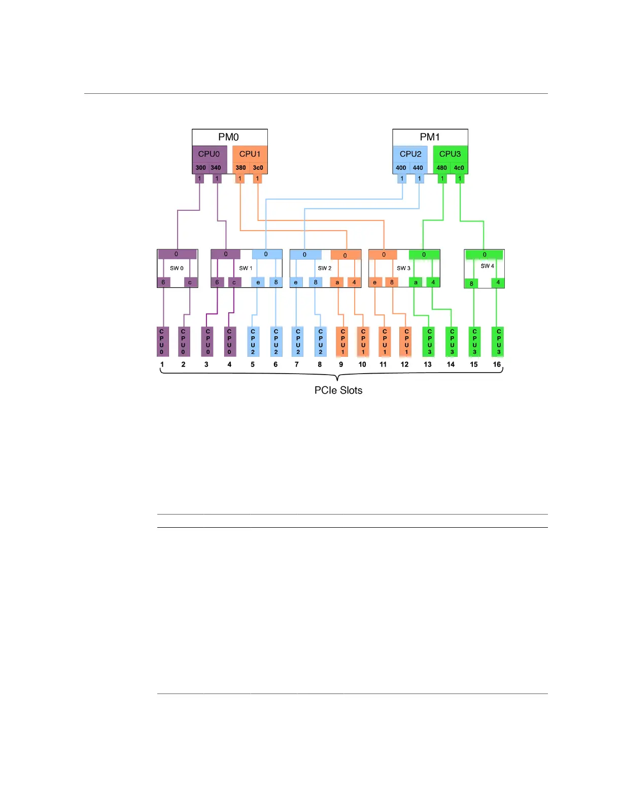
This diagram illustrates the root complex connections between the four CPUs and the 16 PCIe
I/O slots. Each CPU supports two I/O root complex fabrics. Each root complex connects to two
I/O slots through one of five multiplexing switches.
The port ID values shown in the diagram correspond to the pci@ values reported in the
showdevs command output. For example:
PM CPU Switch I/O Slot Root Complex Path
0 0 0 1 /pci@300/pci@1/pci@0/pci@6
0 0 0 2 /pci@300/pci@1/pci@0/pci@c
0 0 1 3 /pci@340/pci@1/pci@0/pci@6
0 0 1 4 /pci@340/pci@1/pci@0/pci@c
1 2 1 5 /pci@400/pci@1/pci@0/pci@e
1 2 1 6 /pci@400/pci@1/pci@0/pci@8
1 2 2 7 /pci@440/pci@1/pci@0/pci@e
1 2 2 8 /pci@440/pci@1/pci@0/pci@8
0 1 2 9 /pci@380/pci@1/pci@0/pci@a
0 1 2 10 /pci@380/pci@1/pci@0/pci@4
0 1 3 11 /pci@3c0/pci@1/pci@0/pci@e
0 1 3 12 /pci@3c0/pci@1/pci@0/pci@8

 Loading...