Chapter 7 Appendix — Installing the Interface Board (optional)
ENGLISH - 321
Installing the Interface Board (optional)
This projector is equipped with one SLOT NX-specication slot.
The input for HDMI, DVI-D, and SDI can be added by installing the optional Interface Board in the slot.
Requesting a qualied technician to install or remove the optional Interface Board is recommended. A malfunction
may occur due to static electricity. Consult your dealer.
Before installing or removing
f Always turn off the power of the projector before installing or removing the Interface Board.
g Always follow the procedure of “Switching off the projector” (x page 78) when turning off the power.
f Do not touch the connector section of the Interface Board directly with your hands.
g The component may be damaged by the static electricity.
f Remove the static electricity from your body by touching to surrounding metal, etc., in advance to prevent the
static electricity damage.
f Take care not to get injured when installing or removing the Interface Board.
g Hands may be injured by the opening of the blank slot or the edge of the bracket of the Interface Board.
f When installing the Interface Board to the slot, insert it into the connector straight and slowly.
g It may not operate or cause malfunction if it is not correctly installed.
f The gure indicating the installation and removal of the Interface Board is using the Interface Board for 12G-SDI
(Model No.: ET-MDN12G10) as an example.
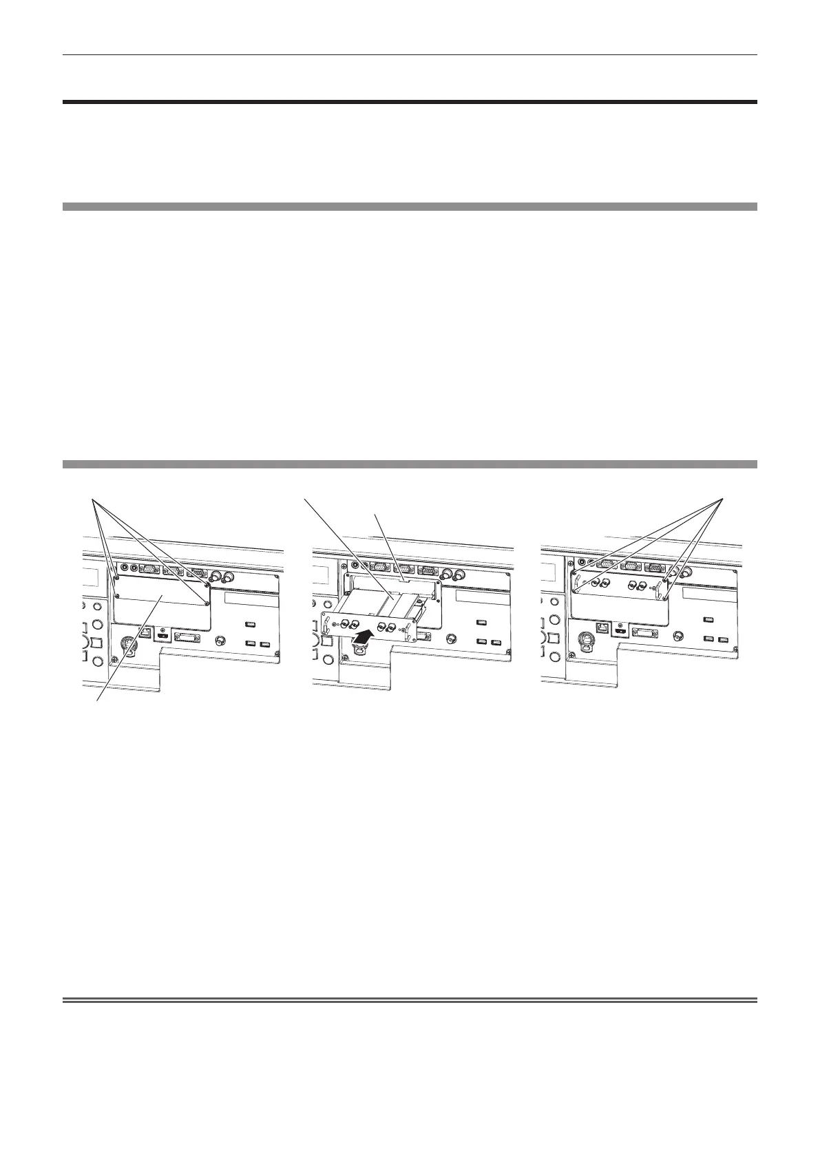
How to install the Interface Board
Screws (4 locations) Screws (4 locations)
Salient
Guide groove
Slot cover
Fig. 1 Fig. 2 Fig. 3
1) Remove the slot cover. (Fig. 1)
f Remove the four screws xing the slot cover by rotating counterclockwise with a Phillips screwdriver. The
removed screws are used to x the Interface Board.
f When removing the fourth screw, hold the slot cover with your hand so it will not fall.
f To replace from other Interface Board, remove the Interface Board following the procedure in “How to
remove the Interface Board” (x page 322).
2) Install the Interface Board to the projector. (Fig. 2)
f Insert the guide groove of the Interface Board aligned to the salient of the slot. Insert the bracket rmly all
the way in.
3) Fix the Interface Board. (Fig. 3)
f Tighten and x with the four screws removed in Step 1).
Attention
f The removed slot cover is required when the unnecessary Interface Board is removed. Store it so it can be attached in the future.
 Loading...