Chapter 1 Preparation — About your projector
34 - ENGLISH
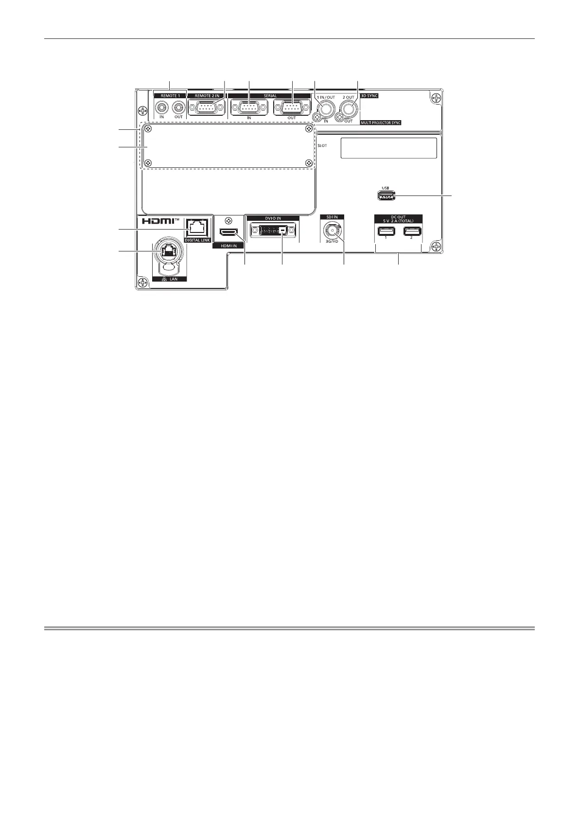
r Connecting terminals
1
14
5 62 3
12 13
4
11
7
8
15
9
10
1 <REMOTE 1 IN> terminal/<REMOTE 1 OUT> terminal
These are terminals to connect the remote control for serial
control in a multiple projector environment.
2 <REMOTE 2 IN> terminal
This is a terminal to remotely control the projector using the
external control circuit.
3 <SERIAL IN> terminal
This is the RS-232C compatible terminal to externally control
the projector by connecting a computer.
4 <SERIAL OUT> terminal
This is a terminal to output the signal connected to the <SERIAL
IN> terminal.
5 <MULTI PROJECTOR SYNC IN> terminal/<3D SYNC 1 IN/
OUT> terminal (dual purpose)
This terminal is used to connect multiple projectors when
balancing the contrast as a combined screen or synchronizing
the effects using the shutter function including the fade in/fade
out with a system using multiple projectors.
This terminal is also used to input or output control signals
when using the projector in 3D systems.
6 <MULTI PROJECTOR SYNC OUT> terminal/<3D SYNC 2
OUT> terminal (dual purpose)
This terminal is used to connect multiple projectors when
balancing the contrast as a combined screen or synchronizing
the effects using the shutter function including the fade in/fade
out with a system using multiple projectors.
This terminal is also used to output control signals when using
the projector in 3D systems.
7 Slot (<SLOT>)
There is a SLOT NX-specication slot to install the optional
Interface Board internally.
8 Slot cover
9 <DIGITAL LINK> terminal
This is a terminal to connect a device that transmits video signal
via the LAN terminal. Also, this is the LAN terminal to connect to
the network.
10 <LAN> terminal
This is the LAN terminal to connect to the network.
This terminal is compatible with the etherCON
®
series cable
connector (NE8MX*, NE8MC*) of Neutrik.
11 <HDMI IN> terminal
This is a terminal to input HDMI signal.
12 <DVI-D IN> terminal
This is a terminal to input DVI-D signal.
13 <SDI IN> terminal
This is a terminal to input SDI signal.
14 <DC OUT 1> terminal/<DC OUT 2> terminal
This is the USB terminal dedicated for power supply. (DC 5 V,
total 2 A)
Use this terminal when a power supply is required to wireless
display adapters and wireless LAN/Ethernet converters, etc.
15 <USB> terminal
This is a terminal to connect the USB memory when using the
data cloning function or rmware update function. (x pages
271, 275)
This is also the terminal to connect the optional Wireless
Module (Model No.: AJ-WM50 Series) when the projector is
connected via wireless LAN. (x page 229)
Note
f When a LAN cable is directly connected to the projector, the network connection must be made indoors.
f To transmit the Ethernet and serial control signals using the <DIGITAL LINK> terminal, set the [NETWORK] menu → [ETHERNET TYPE] to
[DIGITAL LINK] or [LAN & DIGITAL LINK].
f To transmit the Ethernet signal using the <LAN> terminal, set the [NETWORK] menu → [ETHERNET TYPE] to [LAN] or [LAN & DIGITAL
LINK].
f The <DIGITAL LINK> terminal and the <LAN> terminal are connected inside of the projector when the [NETWORK] menu → [ETHERNET
TYPE] is set to [LAN & DIGITAL LINK]. Do not directly connect the <DIGITAL LINK> terminal and the <LAN> terminal using a LAN
cable. Construct the system so that it is not connected to the same network via the peripherals such as the hub or the twisted-pair-cable
transmitter.
f Power can be supplied using the <DC OUT 1> terminal and the <DC OUT 2> terminal even when the projector is in the standby status.

 Loading...