Chapter 2 Getting Started — Setting up
42 - ENGLISH
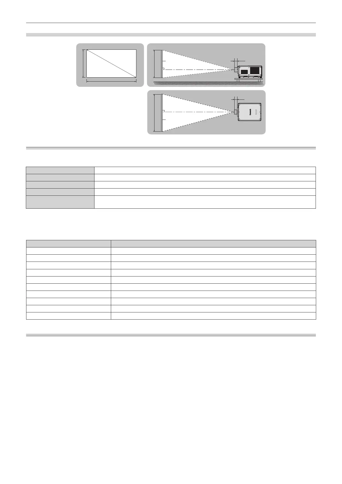
Figure of projected image and throw distance
SD
L (LW/LT)
L1
L1
L (LW/LT)
SW SH
SH
SW
Projected image
Screen
Screen
Note
f This illustration is prepared on the assumption that the projected image size and position have been aligned to t full in the screen.
f This illustration is not in accurate scale.
SH Projected image height
SW Projected image width
SD Projected image size
L
*1
(LW/LT)
*2
Projection distance (distance from the front end of the projection lens to the screen)
L1
Lens protrusion dimension (distance from the front surface of the projector to the front end of the projection
lens)
*1 For details about calculating the projection distance, refer to “Formula for calculating the projection distance per projection lens” (x page 54).
*2 LW: Minimum projection distance when the Zoom Lens is used
LT: Maximum projection distance when the Zoom Lens is used
(Unit: m)
Projection lens Model No. Lens protrusion dimension (L1) (approximate value)
ET-D3LEW10 0.210
ET-D75LE10 0.125
ET-D3LES20/ET-D75LE20 0.121
ET-D3LET30 0.178
ET-D75LE30 0.121
ET-D3LET40 0.135
ET-D75LE40 0.135
ET-D3LEW50/ET-D75LE50 0.203
ET-D3LEW60/ET-D75LE6 0.212
ET-D3LET80/ET-D75LE8 0.262
Note
f For the adjustment range of the projected image position with the lens shift, refer to “Lens shift range” (x page 88).
 Loading...