High−speed Counter/Pulse Output/ PWM OutputFP0
9 − 23
9.4 Pulse Output Function
Pulse output instruction (F169)
This instruction is for JOG operation by obtaining a pulse from the desired output when
the execution condition (trigger) turns on.
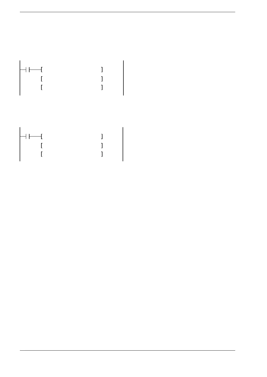
X2
F0 MV, H112, DT200
F0 MV, K300, DT201
F169 PLS, DT200, H0
While X2 is in the on state, a pulse of 300 Hz with a duty ratio of 10% is output from Y0.
At this time, directional output (Y2) is off and the count of the elapsed value for the
high−speed counter CH0 (DT9044 and DT9045/DT90044 and DT90045) increases.
X6
F0 MV, H123, DT200
F0 MV, K700, DT201
F169 PLS, DT200, H1
While X6 is in the on state, a pulse of 700 Hz with a duty ratio of 10% is output from Y1.
At this time, directional output (Y3) is off and the count of the elapsed value for the
high−speed counter CH1 (DT9048 and DT9049/DT90048 and DT90049) decreases.
High−speed counter control instruction (F0)
This instruction is used for resetting the built−in high−speed counter, stopping the pulse
outputs, and setting and resetting the near home input.
Specify this instruction together with the F0 (MV) instruction and the special data
register DT9052/DT90052.
Once this instruction is executed, the settings will remain until this instruction is
executed again.
Operations that can be performed with this instruction
Clear controls (stopping the pulse outputs) from high−speed counter instructions F166
to F170.
Near home processing for home return operations.