14-30
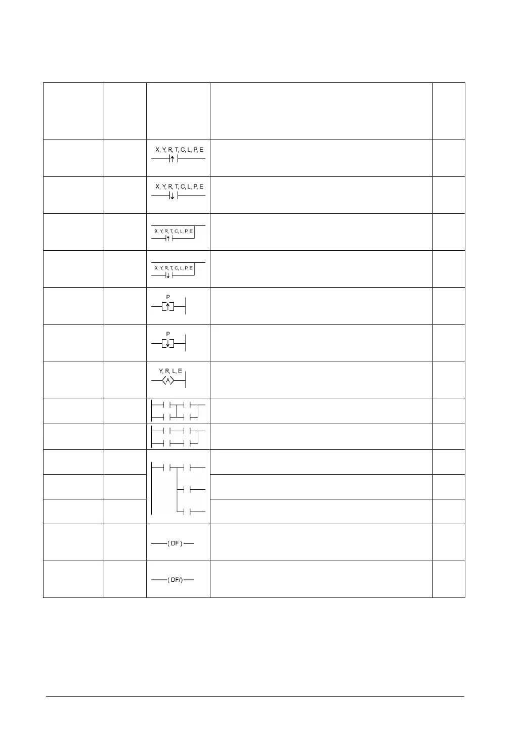
Name Boolean Symbol Description
Steps
Note1)
Leading
edge AND
AN↑ Connects a Form A (normally open) contact serially only
for one scan when the leading edge of the trigger is
detected.
2
Trailing edge
AND
AN↓ Connects a Form A (normally open) contact serially only
for one scan when the trailing edge of the trigger is
detected.
2
Leading
edge OR
OR↑ Connects a Form A (normally open) contact in parallel only
for one scan when the leading edge of the trigger is
detected.
2
Trailing edge
OR
OR↓ Connects a Form A (normally open) contact in parallel only
for one scan when the trailing edge of the trigger is
detected.
2
Leading
edge out
OT↑
Outputs the operated result to the specified output only for
one scan when leading edge of the trigger is detected. (for
pulse relay)
2
Trailing edge
out
OT↓
Outputs the operated result to the specified output only for
one scan when trailing edge of the trigger is detected. (for
pulse relay)
2
Alternative
out
ALT
Inverts the output condition (on/off) each time the leading
edge of the trigger is detected.
3
AND stack
ANS
Connects the multiple instruction blocks serially.
1
OR stack
ORS
Connects the multiple instruction blocks in parallel.
1
Push stack
PSHS
Stores the operated result up to this instruction.
1
Read stack
RDS
Reads the operated result stored by the PSHS instruction.
1
Pop stack
POPS
Reads and clears the operated result stored by the PSHS
instruction
1
Leading
edge
differential
DF
Turns on the contact for only one scan when the leading
edge of the trigger is detected.
1
Trailing edge
differential
DF/
Turns on the contact for only one scan when the trailing
edge of the trigger is detected.
1
Note1) In the FP2/FP2SH/FP10SH, when using X1280, Y1280, R1120 (special internal relay included),
L1280, T256, C256 or anything beyond for the ST, ST/, OT, AN, AN/, OR and OR/ instructions,
the number of steps is shown in parentheses. Also, in the FP2/FP2SH/FP10SH, when a relay
number has an index modifier, the number of steps is shown in parentheses.