Parker EME
Compax3 device description
I11 T11 192-120101 N6 - March 2004 27
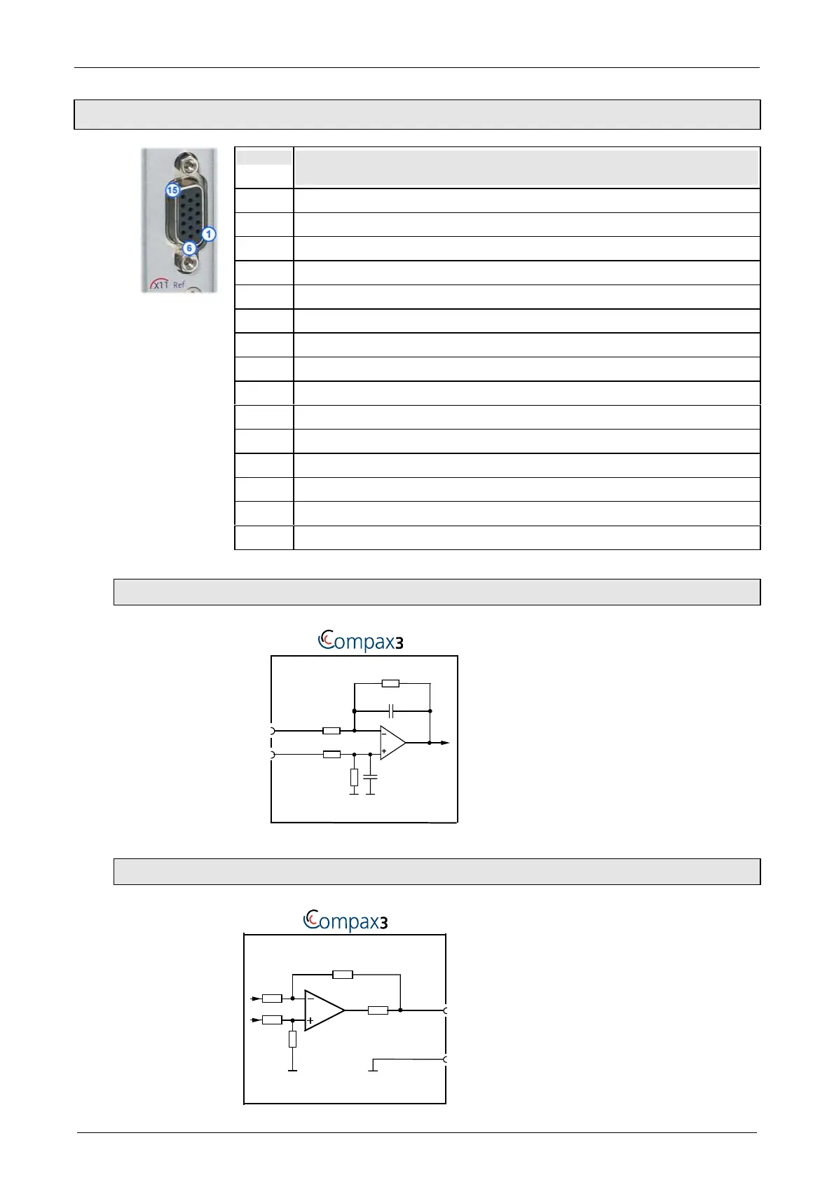
3.1.9. Analog / Encoder (plug X11)
PIN X11 Reference
High Density Sub D
1 +24V (output for encoder) max. 70mA
2 Reserved
3 D/A monitor channel 1 (±10V, 8-bit resolution)
4 D/A monitor channel 0 (±10V, 8-bit resolution)
5 +5V (output for encoder) max. 150mA
6
A/ (Encoder simulation)
7
A (Encoder simulation)
8
B (Encoder simulation)
9 Reserved
10 Reserved
11 Reserved
12
B/ (Encoder simulation)
13
N/ (Encoder simulation)
14
N (Encoder simulation)
15 GND
3.1.9.1 Wiring of the analog input
10nF
2.2K
Ω
10K
Ω
Ain+
2.2K
Ω
X11/9
10K
Ω
10nF
Ain-
X11/11
3.1.9.2 Wiring of analog outputs
+/-10V/1mA
(max: 3mA)
X11/3
X11/15
332Ω
X11/4
 Loading...


