Compax3 device description
28 I11 T11 192-120101 N6 - March 2004
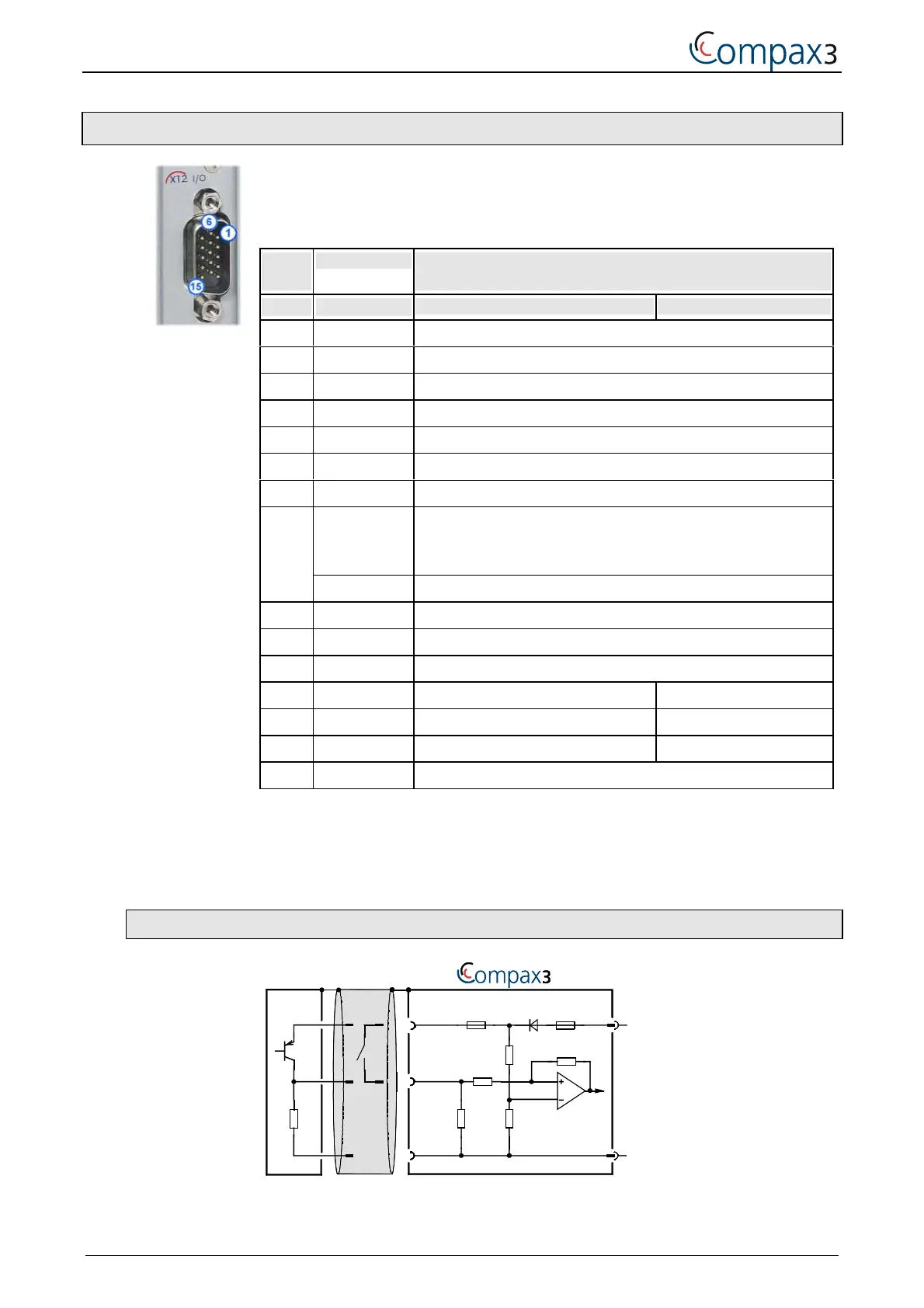
3.1.10. Digital inputs/outputs (plug X12)
The assignment of X12 depends on the operating mode "Normal or Commissioning
Mode".
Only 4 motion profiles can be selected in commissioning mode. The inputs
"Manual+" and "Manual-" are available for this.
PIN
X12/
Input/output I/O /X12
High density/Sub D
Normal mode Commissioning mode
1 O +24VDC output (max. 400mA)
2 O0 No fault
3 O1 Position reached (max. 100 mA)
4 O2 No power output stage current (max. 100mA)
5 O3 Motor stationary with current, with setpoint 0 (max. 100mA)
6I0 No stop
7 I1 Start (edge)
I2="1": Quit (positive edge) / Energize the motor
The address of the current positioning data record is newly read
in.
8
I2="0": Motor deenergized with delay
9 I3 Address 0
10 I4 Address 1
11 I 24V input for the digital outputs Pins 2 to 5
12 I5 Address 2 Manual+
13 I6 Address 3 Manual-
14 I7 MN-Ini* / Address 4 MN-Ini*
15 O Gnd 24 V
*Machine home proximity switch only when the corresponding mode has been
selected. 15 motion profiles (address 0-3) and machine zero run are then possible.
All inputs and outputs have 24V level.
Maximum capacitive load on the outputs: 50 nF (max. 4 Compax3 inputs)
3.1.10.1 Input wiring of digital inputs
24V
0V
100K
Ω
X12/1
X12/6
X12/15
10K
Ω
22K
Ω
22K
Ω
22K
Ω
SPS/PLC
X4/1
X4/2
F2
F1
 Loading...


