Parker EME
Compax3 device description
I11 T11 192-120101 N6 - March 2004 29
The circuit example is valid for all digital inputs!
F1: Delayed action fuse
F2: Quick action electronic fuse; can be reset by switching the 24VDC supply off
and on again.
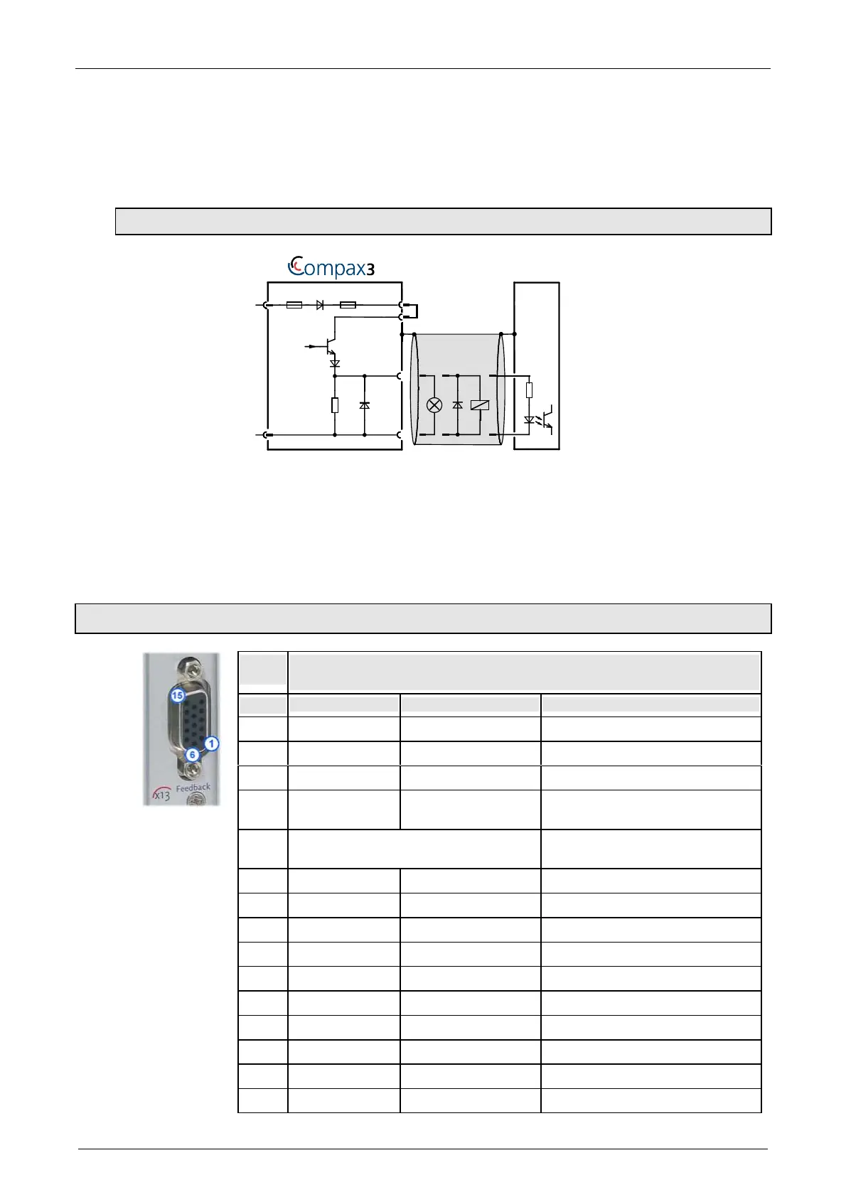
3.1.10.2 Output wiring of digital outputs
24V
0V
X12/2
18.2K
Ω
X12/15
X12/1
X12/11
SPS/
PLC
X4/1
X4/2
F2
F1
The circuit example is valid for all digital outputs!
The outputs are short circuit proof; a short circuit generates an error.
F1: Delayed action fuse
F2: Quick action electronic fuse; can be reset by switching the 24VDC supply off
and on again.
3.1.11. Resolver / Feedback (connector X13)
PIN
X13
Feedback /X13
High Density /Sub D (dependent on the Feedback Module)
Resolver (F10) SinCos (F11) Direct drives (F12)
1 res. res. Sense -
2 res. res. Sense +
3 GND GND Hall1
4 REFres+ Vcc (+8V) Vcc (+5V) (controlled on the encoder
side) max. 200mA load
5 +5V (for temperature sensor) +5V (for temperature and hall
sensors)
6 CLKfbk CLKfbk Hall2
7 SIN- SIN- SIN- / A- (Encoder)
8 SIN+ SIN+ SIN+ / A+ (Encoder)
9 CLKfbk/ CLKfbk/ Hall3
10 Tmot Tmot Tmot
11 COS- COS- COS- / B- (Encoder)
12 COS+ COS+ COS+ / B+ (Encoder)
13 res. DATAfbk N+
14 res. DATAfbk/ N-
15 REFres- GND (Vcc) GND (Vcc)
 Loading...


