EasyManuals Logo

Parker Compax3 S150 V4 User Manual

Parker Compax3 S150 V4
150 pages
To Next Page IconTo Next Page
To Previous Page IconTo Previous Page
Page #64 background imageLoading...
Page #64 background image
Setting up Compax3
64 I11 T11 192-120101 N6 - March 2004
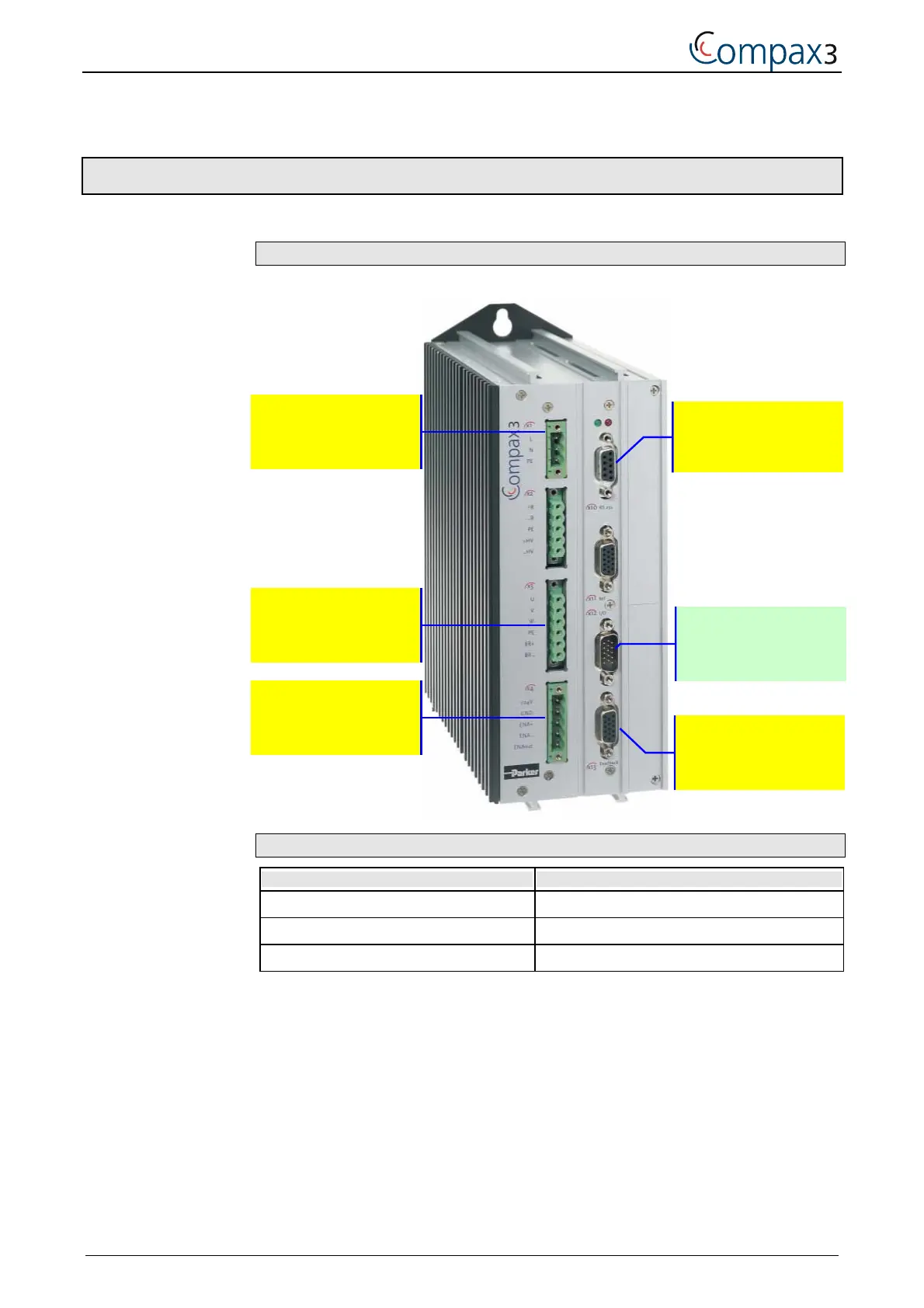
4.2 Test commissioning Compax3
Required wiring:
Operational enable of the servo controller:
Plug/Pin Assignment
X12/6 (no STOP) = 24V DC (jumper to X12/1)
X12/8 (Energize the motor) = 24V DC (jumper to X12/1)
X4/3 (Enable power output stage) = 24V DC (jumper to X4/1)
X10 to PC
RS232 / RS485
X12 (see below)
Inputs/Outputs
X13 to the moto
r
position transmitter
X1: Mains supply
/1: 230V AC +10%
/2: 0V
/3: PE
X3
Motor / Brake
X4: 24VDC
/3: enable with
24VDC

Table of Contents

Other manuals for Parker Compax3 S150 V4

Questions and Answers:

Question and Answer IconNeed help?

Do you have a question about the Parker Compax3 S150 V4 and is the answer not in the manual?

Parker Compax3 S150 V4 Specifications

General IconGeneral
Output Current150 A
Control TypeDigital
SeriesCompax3
ModelS150 V4
Enclosure RatingIP20
Communication InterfacesCANopen, RS-232, RS-485
Feedback OptionsResolver
Protection FeaturesOvercurrent, Overvoltage, Undervoltage, Overtemperature, Short Circuit
Relative Humidity5 to 95% non-condensing
Operating Temperature0 to +45 °C (32 to 113 °F)

Related product manuals