Parker EME
Setting up Compax3
192-120114 N5 C3I22T11 June 2008 115
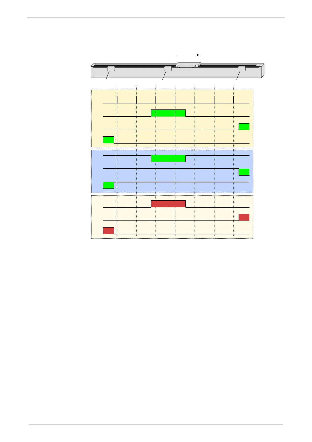
Example axis with the initiator signals
4
12 3
5
6
7
8
9
10
11
-
+
12
13
14
1:
Direction reversal / end switch on the negative end of the travel range
(the assignment of the reversal / end switch inputs (see page 132) to travel range
side ca
n be changed).
2: Machine zero initiator (can, in this example, be released to 2 sides)
3:
Direction reversal / end switch on the positive end of the travel range
(the assignment of the reversal / end switch inputs (see page 132) to travel range
side ca
n be changed).
4: Positive direction of movement
5: Signals of the motor zero point (zero pulse of the motor feedback)
6:
Signal of the machine zero initiator
(without inversion of the initiator logic (see page 132)).
7:
Sign
al of the direction reversal resp. end switch on the positive end of the travel range
(without inversion of the initiator logic).
8:
Signal of the direction reversal / resp. end switch on the negative end of the travel range
(without inversion of the initiator logic).
9:
Signal of the machine zero initiator
(with inversion of the initiator logic (see page 132)).
10:
Sign
al of the direction reversal / resp. end switch on the positive end of the travel range
(with inversion of the initiator logic).
11:
Signal of the direction reversal / resp. end switch on the negative end of the travel range
(with inversion of the initiator logic).
12: Logic state of the home switch (independent of the inversion)
13:
Logic state of the direction reversal resp. end switch on the positive end of the travel
range (independent of the inversion)
14:
Logic state of the direction reversal resp. end switch on the negative end of the travel
range (independent of the inversion)
The following principle images of the individual machine zero modes always refer
to the logic state (12, 13, 14) of the switches.

 Loading...


