EasyManua.ls Logo

Parker Compax3 Series User Manual

Parker Compax3 Series
414 pages
To Next Page IconTo Next Page
To Previous Page IconTo Previous Page
Page #302 background imageLoading...
Page #302 background image
Communication
C3I22T11
302 192-120114 N5 C3I22T11 June 2008
5.2.3. Binary record
The binary record with block securing is based on 5 different telegrams:
2 request telegrams which the control sends to Compax3 and
3 response telegrams which Compax3 returns to the control.
Telegram layout
Basic structure:
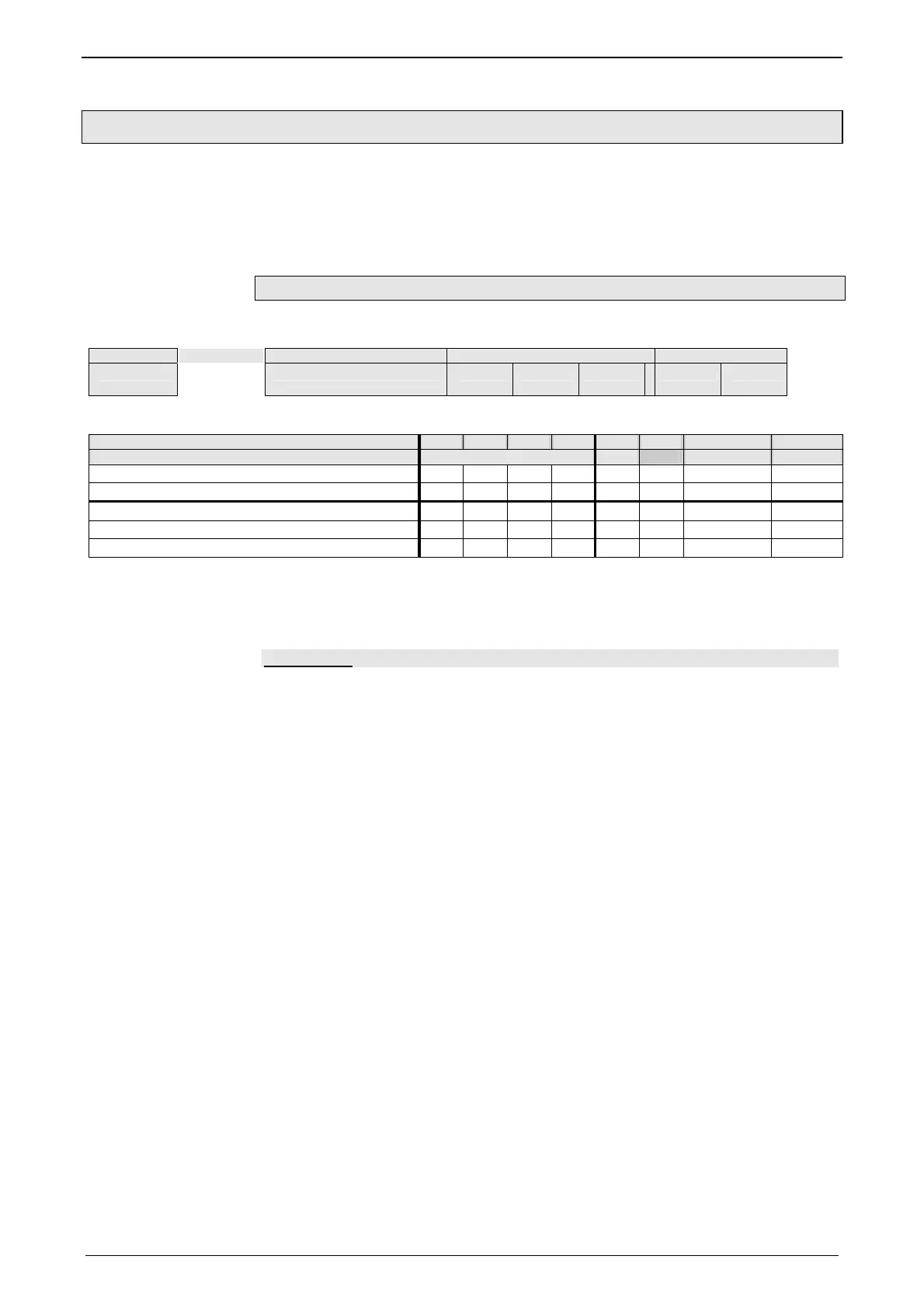
Start code address Number of data bytes - 1 Data block securing
SZ A L D0 D1 ...
D
n
Crc(Hi) Crc(Lo)
The start code defines the frame type and is composed as follows:
Bit 7 6 5 4 3 2 1 0
Frame type Frame identification PLC Gateway address
RdObj Read object 1 0 1 0 x 1 x x
WrObj Write object 1 1 0 0 x 1 x x
Rsp Answer 0 0 0 0 0 1 0 1
Ack Positive command acknowledgement 0 0 0 0 0 1 1 0
Nak Negative command acknowledgement 0 0 0 0 0 1 1 1
Bits 7, 6, 5 and 4 of the start code form the telegram identification; Bit 2 is always
”1”.
Bits 3, 1 and 0 have different meanings for the request and response telegrams.
The address is only necessary for RS484.
-> Compax3
the address bit (Bit 0 = 1 ) shows if the start code is followed by an address
(only for RS485; for RS232 Bit 0 = 0)
the gateway bit (Bit 1 = 1) shows if the message is to be passed on.
(Please set Bit 1 = 0, as this function is not yet available)
the PLC bit (Bit 3 = 1 ) allows access to objects in the PLC/Pop format
U16, U32: for integer formats (see bus formats: Ix, Ux, V2)
IEEE 32Bit Floating Point: for broken formats (bus formats: E2_6, C4_3, Y2, Y4;
without scaling)
With Bit 3 = 0 the objects are transmitted in the DSP format.
DSP formats:
24 Bit = 3 Bytes: Integer INT24 or Fractional FRACT24
48 Bit = 6 Bytes: Real REAL48 (3 Byte Int, 3 Byte Fract) / Double Integer DINT48
/ Double Fractional DFRACT48
Request telegrams

Table of Contents

Other manuals for Parker Compax3 Series

Question and Answer IconNeed help?

Do you have a question about the Parker Compax3 Series and is the answer not in the manual?

Parker Compax3 Series Specifications

General IconGeneral
Enclosure RatingIP20
Control ModesSpeed, Torque, Position
Communication InterfacesCANopen, EtherCAT
Feedback OptionsIncremental Encoder, Resolver
Protection FeaturesOvercurrent, Overvoltage, Undervoltage, Overtemperature, Short Circuit
Cooling MethodForced Air, Natural Convection
Relative Humidity5 to 85 %, non-condensing
Operating Temperature0 to +45 °C (derating may apply above 40°C)

Summary

1. Introduction

1.1 Device assignment

Describes the devices this manual applies to, including Compax3S, Compax3H, Compax3M, and Compax3MP models.

1.2 Type specification plate

Explains the device description on the type specification plate, detailing designations, interface, and options.

1.4 Safety Instructions

Covers general hazards, safety-conscious working practices, and special safety instructions.

1.6 Conditions of utilization

Specifies conditions for CE-conform operation, UL certification, and supply networks.

2. Compax3 Xxxx I22T11 Introduction

Configuration

Mentions PC configuration via Compax3 ServoManager and general proceedings.

3. Compax3 device description

3.1 Meaning of the status LEDs - Compax3 axis controller

Explains the function of status LEDs on the Compax3 axis controller, indicating device states.

3.3 Connections of Compax3S

Describes the connectors and pin assignments for the Compax3S series devices.

3.5 Compax3MP/Compax3M connections

Details the front connector and device bottom connections for Compax3MP and Compax3M.

3.7 Communication interfaces

Explains communication methods including RS232, RS485, and DeviceNet connectors.

3.8 Signal interfaces

Describes resolver, encoder, analog, and digital input/output signal interfaces.

3.10 Safety function – safety torque off – Compax3S

Details the safety torque off function for Compax3S, including principles and application.

3.11 Compax3M with safety option S1: Safe torque off

Explains the safe torque off option for Compax3M, including terms, description, and advantages.

4. Setting up Compax3

4.1 Configuration

Covers general configuration steps, including PC requirements and test commissioning.

4.3 Optimization

Details various optimization tools and procedures like Scope, Controller optimization, and Load identification.

5. Communication

5.1 Compa3 communication variants

Lists different communication methods including RS232, RS485, USB, and modem connections.

5.4 DeviceNet

Covers DeviceNet configuration, error reactions, operating modes, and object classes.

6. Status values

6.1 D/A-Monitor

Explains how to output status values via the D/A monitor channels and includes an example.

7. Error

7.1 Error list

Provides information on error reactions, error codes, and how to view the error history.

8. Order code

8.1 Order code device: Compax3

Details the order code structure for Compax3 devices, including model, current, and interface options.

9. Compax3 Accessories

9.1 Parker servo motors

Describes direct drive, linear, and torque motors supported by Compax3.

9.2 EMC measures

Covers EMC measures including mains filters and motor output filters.

9.3 Connections to the motor

Details resolver, SinCos, EnDat cables, and motor cable connections.

9.4 External braking resistors

Lists external braking resistors, their permissible pulse powers, and dimensions.

9.9 Interface Cables

Lists various interface cables including RS232, RS485, and USB cables.

10. Specifications

Mains connection Compax3S0xxV2 1AC

Provides mains connection specifications for Compax3S0xxV2 1AC devices.

Mains connection Compax3S1xxV2 3AC

Gives mains connection specifications for Compax3S1xxV2 3AC devices.

Mains connection Compax3SxxxV4 3AC

Details mains connection specifications for Compax3SxxxV4 3AC devices.

Mains connection Compax3MP10D6

Lists mains connection specifications for Compax3MP10D6 devices.

Output data Compax3Mxxx at 3*400VAC

Provides output specifications for Compax3Mxxx devices at 3*400VAC.

Resulting nominal and peak currents depending on the switching frequency

Details nominal and peak currents based on switching frequency for various Compax3 models.

Related product manuals