Compax3 device description C3I22T11
78 192-120114 N5 C3I22T11 June 2008
3.10 Safety function – safety torque off – Compax3S
In this chapter you can read about:
Safe standstill with Compax3 principle...............................................................................78
Devices with the "Safe Standstill" safety function ..............................................................79
Safety instructions for the ”safety torque off” function ........................................................80
Application example for ”safe standstill”.............................................................................81
Compax3S is equipped with the "safety torque off" safety feature.
The ”protection against unexpected start-up” described in EN1037 can be imple-
mented with this feature.
3.10.1. Safe standstill with Compax3 principle
To ensure safe protection against a motor starting up unexpectedly, the flow of
current to the motor and thus to the power output stage must be prevented.
This is accomplished for Compax3 with two measures independent of each other
(Channel 1 and 2), without disconnecting the drive from the power supply:
Channel 1:
Activation of the power output stage can be disabled in the Compax3 controller by
means of a digital input or with a fieldbus interface (depending on the Compax3
device type) (deactivation of the energize input).
Channel 2:
The power supply for optocouplers and drivers of power output stage signals is
disconnected by a safety relay activated by the enable input "ENAin"(X4/3) and
equipped with force-directed contacts. This prevents control signals from being
transferred to the power output stage.
The “Safe Standstill” safety function as defined by EN 954-1 Category 3
is only possible if both channels are used.
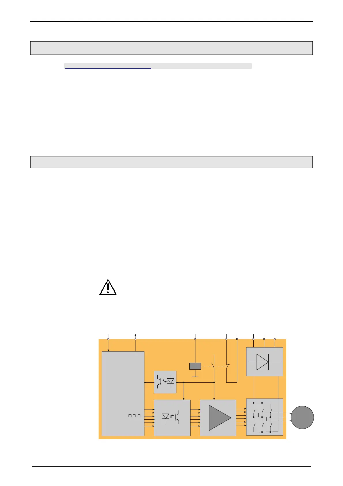
Circuit diagram illustrating working principle:
controller
safety relay
X4/3 X4/5X4/4
X1/1 X1/2 X1/3
Feedback
power
supply
power
supply
motor
Channel 1 Channel 2
L1 L2 L3Energise
Controller
Feedback
ENAin
(Enable)
Feedback
Compax3

 Loading...


