Parker EME
Compax3 device description
192-120114 N5 C3I22T11 June 2008 65
3.8 Signal interfaces
In this chapter you can read about:
Resolver / Feedback (connector X13)................................................................................65
Analog / Encoder (plug X11) ..............................................................................................66
Digital inputs/outputs (plug X12) ........................................................................................67
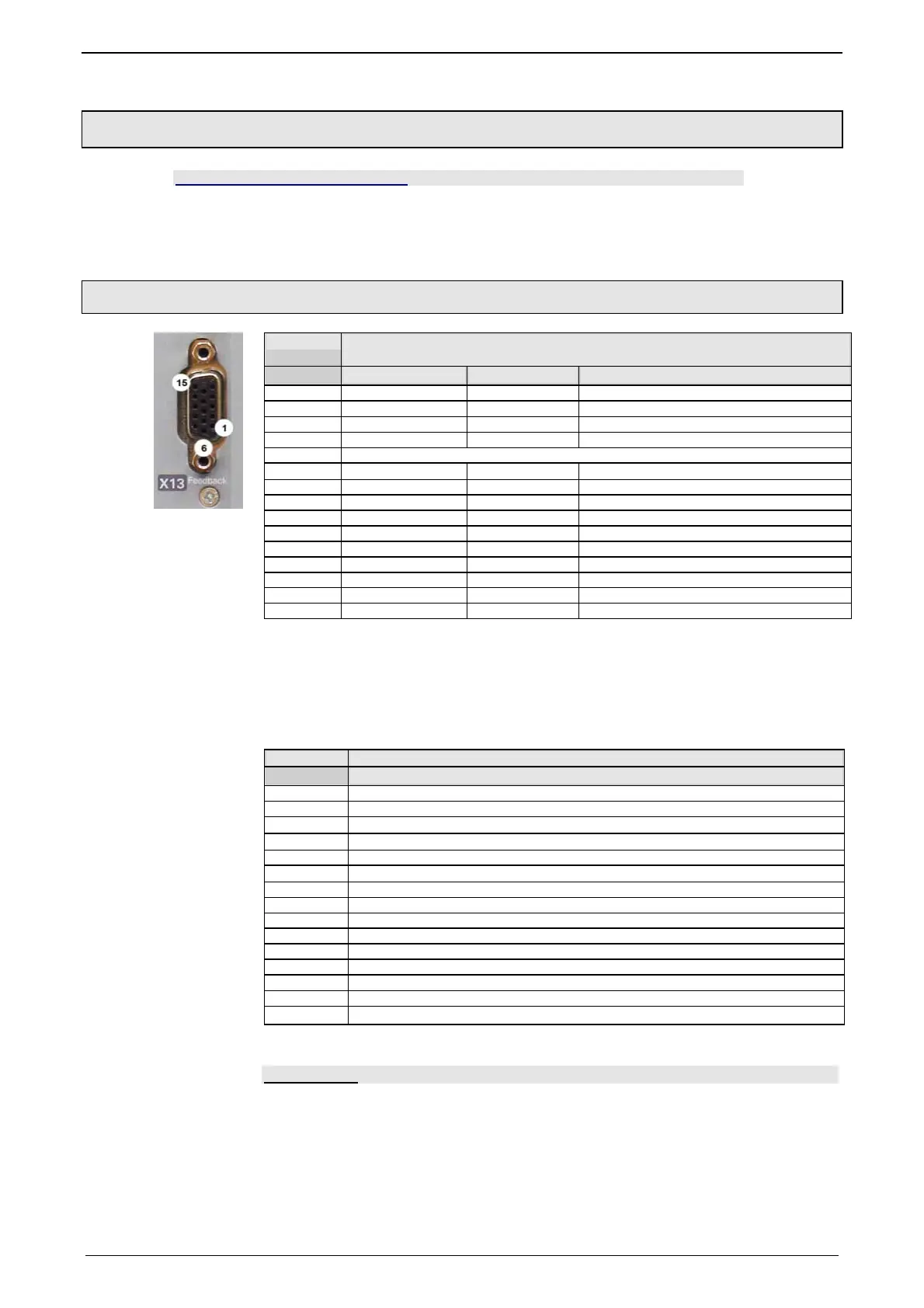
3.8.1. Resolver / Feedback (connector X13)
PIN X13 Feedback /X13 High Density /Sub D
(depending on the Feedback module)
Resolver (F10) SinCos (F11) EnDat 2.1 (F12)
1 Reserved Reserved Sense -*
2 Reserved Reserved Sense +*
3 GND GND Reserved
4 REF-Resolver+ Vcc (+8V) Vcc (+5V) * max. 350mA load
5 +5V (for temperature sensor)
6 Reserved Reserved CLKfbk
7 SIN- SIN- SIN- / A- (Encoder)
8 SIN+ SIN+ SIN+ / A+ (Encoder)
9 Reserved Reserved CLKfbk/
10 Tmot* Tmot* Tmot*
11 COS- COS- COS- / B- (Encoder)
12 COS+ COS+ COS+ / B+ (Encoder)
13 Reserved DATAfbk DATAfbk
14 Reserved DATAfbk/ DATAfbk/
15 REF-Resolver- GND (Vcc) GND (Vcc)
*X13 Pin10 Tmot may not be connected at the same time as X15 (on Compaxx3M).
Resolver cables (see page 356) can be found in the accessories chapter of the
device description.
SinCos
©
- cables (see page 357) can be found in the accessories chapter of the
device description.
EnDat cable GBK38 (see page 358) can be found in the acce
ssories chapter of
the device description
PIN X13 Feedback /X13 High Density /Sub D
Direct drives (F12)
1 Sense -*
2 Sense +*
3 Hall1 (digital)
4 Vcc (+5V) * max. 350mA load
5 +5V (for temperatureand Hall Sensors)
6 Hall2 (digital)
7 SIN-, A- (Encoder) or analog Hall sensor
8 SIN+, A+, (Encoder) or analog Hall sensor
9 Hall3 (digital)
10 Tmot*
11 COS-, B- (Encoder) or analog Hall sensor
12 COS+, B+ (Encoder) or analog Hall sensor
13 N+
14 N-
15 GND (Vcc)
*X13 Pin10 Tmot may not be connected at the same time as X15 (on Compaxx3M).
Note on F12:
*+5V (Pin 4) is measured and controlled directly at the end of the line via Sense –
and Sense +.
Maximum cable length: 100m
Pin 4 and Pin 5 must under no circumstances be connected!
Plug in or pull out feedback connector only in switched off state (24VDC switched
off).
Caution!

 Loading...


