EasyManuals Logo

Parker Compax3 Series User Manual

Parker Compax3 Series
414 pages
To Next Page IconTo Next Page
To Previous Page IconTo Previous Page
Page #68 background imageLoading...
Page #68 background image
Compax3 device description C3I22T11
68 192-120114 N5 C3I22T11 June 2008
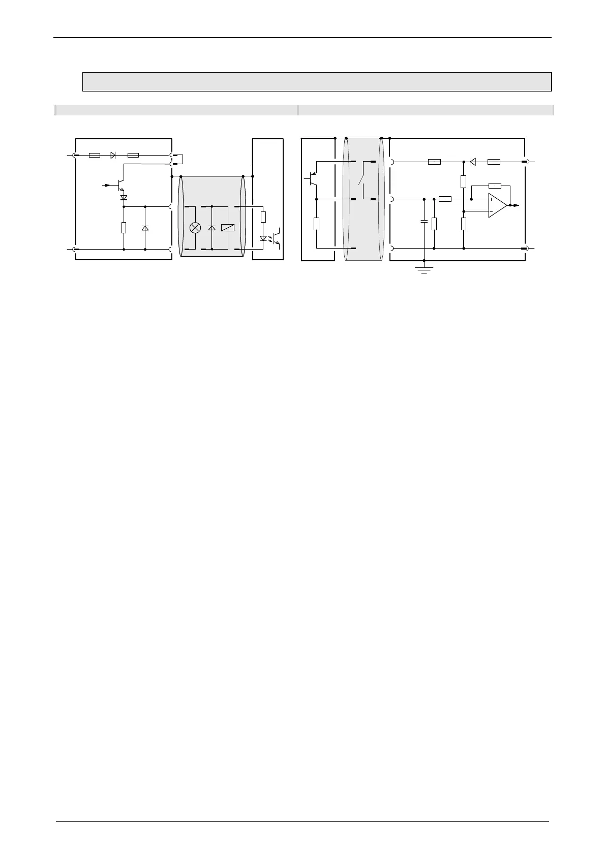
3.8.3.1 Connection of the digital Outputs/Inputs
Wiring of digital outputs Status of digital inputs
24V
0V
X12/2
18.2K
Ω
X12/15
X12/1
X12/11
SPS/
PLC
F2
F1
Compax3
24V
0V
100K
Ω
X12/1
X12/6
X12/15
10K
Ω
22K
Ω
22K
Ω
22K
Ω
SPS/PLC
F2
F1
10nF
Compax3
The circuit example is valid for all digital outputs!
The outputs are short circuit proof; a short circuit
generates an error.
The circuit example is valid for all digital inputs!
Signal level:
> 9.15V = "1" (38,2% of the control voltage applied)
> 8.05V = "0" (33.5% of the control voltage applied)
F1: delayed action fuse
F2: quick action electronic fuse; can be reset by switching the 24VDC supply off and on again.

Table of Contents

Other manuals for Parker Compax3 Series

Questions and Answers:

Question and Answer IconNeed help?

Do you have a question about the Parker Compax3 Series and is the answer not in the manual?

Parker Compax3 Series Specifications

General IconGeneral
Enclosure RatingIP20
Control ModesSpeed, Torque, Position
Communication InterfacesCANopen, EtherCAT
Feedback OptionsIncremental Encoder, Resolver
Protection FeaturesOvercurrent, Overvoltage, Undervoltage, Overtemperature, Short Circuit
Cooling MethodForced Air, Natural Convection
Relative Humidity5 to 85 %, non-condensing
Operating Temperature0 to +45 °C (derating may apply above 40°C)

Related product manuals