Setting up Compax3 C3I22T11
238 192-120114 N5 C3I22T11 June 2008
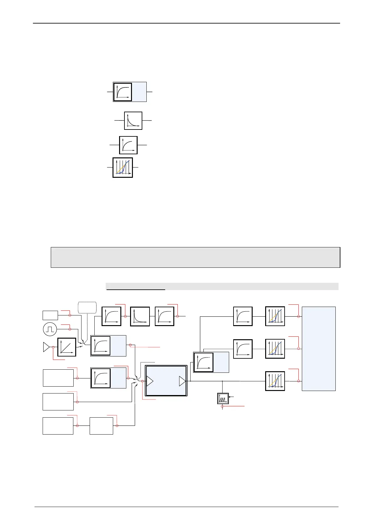
B: Structure image of the signal processing,
D/E: Structure of Gearing
Control structure (see page 212, see page 214, see page 205)
Symbols
TRF
2110.1
Trackingfilter
The displayed filter influences all outputs of the tracking filter.
Number: Object number of the filter characteristic
Differentiator
Output signal = d(input signal)/dt
The output signal is the derivation (gradient) of the input signal
Filter
Number: Object number of the filter characteristic
interpolation
500µs => 125µs
Interpolation
Linear Interpolation.
Values in the 500µs grid are converted into the more exact time
grid of 125µs.
Note:
A setpoint jerk setpoint feedback is not required for external setpoint specificati-
on.
The description of the objects can be found in the object list.
4.3.4.2 Signal filtering for external setpoint specification and electronic
cam
Only Compax3 T40!
C3SM
Wizard
HEDA
interpolation
500s => 125s
interpolation
500s => 125s
interpolation
500s => 125s
C
o
n
t
r
o
l
s
t
r
u
c
t
u
r
e
681.4
682.4
680.4
2110.7
2110.6
TRF
Physical
2107.1
TRF
HEDA
2109.1
+/-10V
B
position
speed
accel
speed
accel
3920.1
3920.7
2020.2
2020.3
2011.4
2011.5
accel
speed
680.10
2020.1(x)
CANSync
PowerLink
EtherCat
Inter-
polator
3921.1 3921.7(x)
680.25
Virtual
Master
SSI
680.12
TRF
SG1
2110.1
685.3
RS
D
E
Structure
of Cam
2000.2
3021.2
3021.1
0
2
1
5

 Loading...


