Parker EME
Compax3 device description
192-120114 N5 C3I22T11 June 2008 57
3.6.6. Mains connection Compax3H
Avoid permanent switching on and off so that the charging connection is not
overloaded.
Mains connection Compax3HxxxV4
Controller type
H050V4 H090V4 H125V4 H155V4
Supply voltage
Three phase 3*400VAC/480VAC
350-528VAC / 50-60Hz
Input current
54Aeff 93Aeff 118Aeff 140Aeff
60A 100A 125A 150A
Maximum fuse rating per
device(=short circuit
rating)
JDDZ class K5,
JDRX class H
JDDZ class H5,
JDRX class H
The terminal block of the drive can be found under the front cover. It is secured
with 2 screws at the bottom of the device. Remove the bottom cover in order to
access the conection clamps.
Make sure that all live parts are covered by the housing after installation.
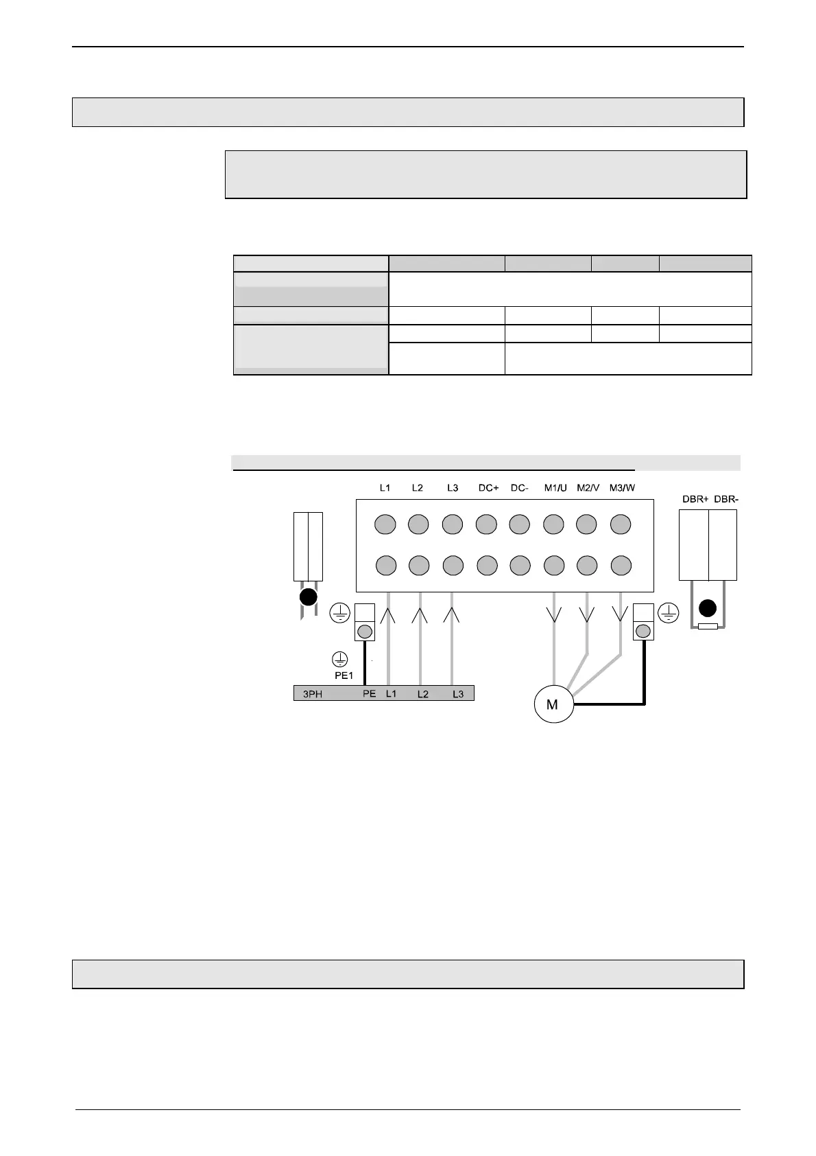
Illustration of the connection clamps exemplarily for all sizes:
2
1
L1, L2, L3: 3 phase mains connection
M1, M2, M3: Motor connections
DC+, DC-: DC link voltage
(1) DBR+ und DBR-: Connection of external braking resistor
(2) AUX1, AUX2: only with C3H1xxV4 external supply (AC) for device ventilator L,
N
All shields must be connected via a cable joint to the cable feedthrough plate.
Braking resistor and cable must be shielded if they are not installed in a control
cabinet.
The standard connection clamps of C3H090V4 and C3H1xxV4 are not suitable
for flat line bars.
3.6.7. Braking resistor / supply voltage C3H
The energy generated during braking operation is absorbed by the Compax3 sto-
rage capacity.
If this capacity is too small, the braking energy must be drained via a braking resi-
stor.
Device protection

 Loading...


