Setting up Compax3 C3I22T11
258 192-120114 N5 C3I22T11 June 2008
4.3.9.6 Measurement of frequency responses
In this chapter you can read about:
Safety instructions concerning the frequency response measurement ........................... 258
Functionality of the measurement.................................................................................... 258
Open/Closed Loop frequency res
ponse measurement ................................................... 260
Excitation Signal .............................................................................................................. 261
Non-linearities and their effects ....................................................................................... 262
Please note that you require a licence hey (see page 250, see page 248) for
this application!
Safety instructions concerning the frequency response measurement
During the measurement of the frequency response, the control is changed and
influenced in multiple ways. You should therefore respect the following notes:
During the measurement, the entire system is excited via a broad frequency
spectrum. This might damage especially sensitive components (such as lenses)
The risk increases with the extent of the excitation. In addition, natural mechani-
cal frequencies may cause an increased excitation of individual components.
The measurement of the frequency response can only be made in the setup
mode with energized controller.
During the current measurement (between start and stop of the measurement),
no write flash may be executed.
In the event of a break in communication during the measurement, the controller
must be switched off and then on again in order to reestablish the original status.
Changes of the controller parameters during the measurement are not permitted.
Those may be overwritten by standard values when the measurement is termina-
ted.
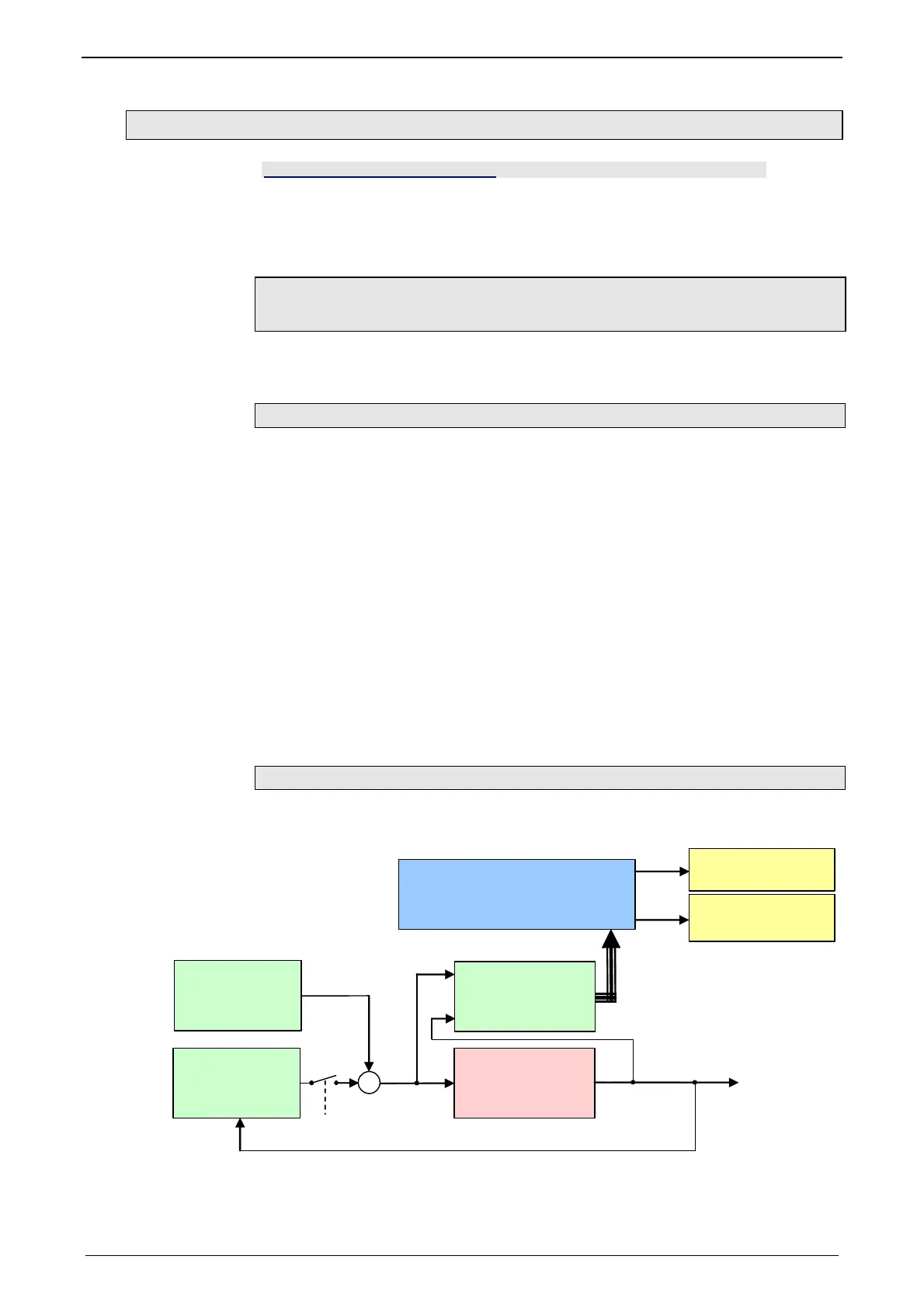
Functionality of the measurement
Basic structure of a frequency response measurement
System S
G
S
Input
Eingangs
Signal u(t)
Output
Ausgangs
Signal y(t)
Signal
Generato
Signal Processing
Signalauswertung
Amplitude spectrum
Aplitudenspektrum
Phase spectrum
Phasenspektrum
V(f)
(f)
Superimposed
überlagertes
S
stem
+
open/closed
Loop
C3 Software-
Oscilloscope
Upload

 Loading...


