Setting up Compax3 C3I22T11
226 192-120114 N5 C3I22T11 June 2008
friction behavior (amplitude of the limit cycle) and on the noise on the following
error (the noise must remain within the deadband).
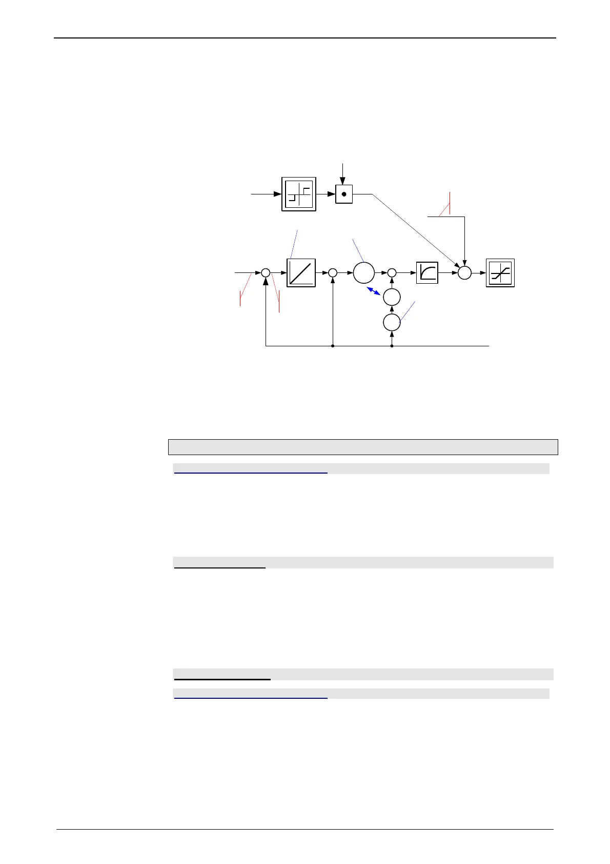
Friction compensation
The activation of the friction compensation (end of the velocity loop)
K
I
pv
K
D
K
-
--
pv
K
T
681.6 Speed
Tracking error
2100.7 Velocity loop - "D" term
2100.2 Stiffness
2100.3 Damping
681.10 Setpoint Speed
688.14 Current &
jerk feed-forward RMS
f(n
SG
, n, O2200.24, Obj. 2200.20)
Filter tracking error
The friction compensation helps the control to surmount static friction at low set-
point speeds. The non linear characteristic line is partly compensted by this and a
smaller deadband can be chosen, which will increase the position accuracy. The
amplitude of the friction compenstion depends on the application and must be cal-
culated if needed. If the value is set too high, corrective movements may result and
the tendency to oscillate is increased.
Commissioning window
In this chapter you can read about:
Load identification............................................................................................................ 226
Setpoint generation.......................................................................................................... 226
Commissioning window
With the aid of the setup window, the drive can be set up in a simple way.
Load identification
If you do not know the mass moment of inertia, it can be determined. For this, you
click on the corresponding button (see setup window no. 13). After the following
parameter entry, the identification can be started via the same button.
For more detailed information on the load identification, see the device help,
chapter "load identification".
This measurement requires the correct EMC or torque constant value Kt.
Setpoint generation
In this chapter you can read about:
Internal setpoint generation ............................................................................................. 227
External setpoint generation ............................................................................................ 228
The setpoints for the control loops are provided in two different ways - internally or
externally. The setpoint generation depends on the technology option of the device.

 Loading...


