Parker EME
Setting up Compax3
192-120114 N5 C3I22T11 June 2008 227
Internal setpoint generation
The internal setpoint generation can be used for the technology option s>T10. In
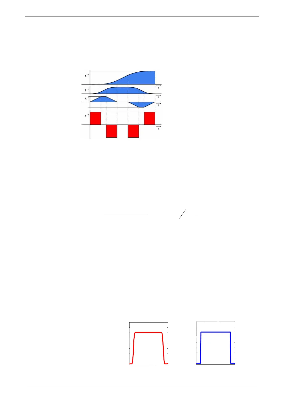
this case, the internal setpoint genertor generates the entire motion profile with
position, velocity, acceleration and jerk.
Motion profile at jerk-controlled setpoint generation
W
a
W
n
W
x
W
x
W
Position
n
W
Velocity
a
W
Acceleration
j
W
Jerk
The drive cannot move randomly through hard profiles, as certain physical limits
exist for the acceleration ability due to the motor physics and the limitation of the
control variable. You must therefore make sure that the set movement corresponds
to the real physics of the motor and of the servo drive.
As a support you can take the following physical correlation.
The calculation of the physically possible acceleration
rotary drives Linear drives
²][2
][][
²][
kgmJ
NmMNmM
rpsa
ges
LA
⋅
=
π
]
][
][][
²
kgm
NFNF
s
m
a
ges
LA
−
=
M
A
: Drive torque of the motor F
A
: Drive force of a linear motor
M
L
: Load torque of the motor F
L
: Load force of a linear motor
J
total
: entire mass moment of inertia m
ges
: Total mass of a linear motor
a: possible acceleration
The generation of the setpoint profile is jerk-controlled and jerk-limited by the speci-
fication of the jerk.
In practice, jerk-limited setpoint generation is important if the items to be moved
must be handled gently. In addition, the service life of the mechanical guiding sy-
stem will be extended. A separate setting of jerk and slope of the deceleration pha-
se also permits overshoot-free positioning in the target position. For this reason, it
is common practice to use higher values for acceleration and jerk in the accelerati-
on phase than in the deceleration phase. In consequence a higher cycle rate can
be achieved.
An additional important reason for the jerk limitation is the excitation of higher fre-
quencies due to the too high jerk in the power density spectrum of the velocity
function.
Jerk=10000°/s
3
Jerk=1000000°/s
3
Time function:

 Loading...


