EasyManuals Logo

Parker Compax3 Series User Manual

Parker Compax3 Series
414 pages
To Next Page IconTo Next Page
To Previous Page IconTo Previous Page
Page #117 background imageLoading...
Page #117 background image
Parker EME
Setting up Compax3
192-120114 N5 C3I22T11 June 2008 117
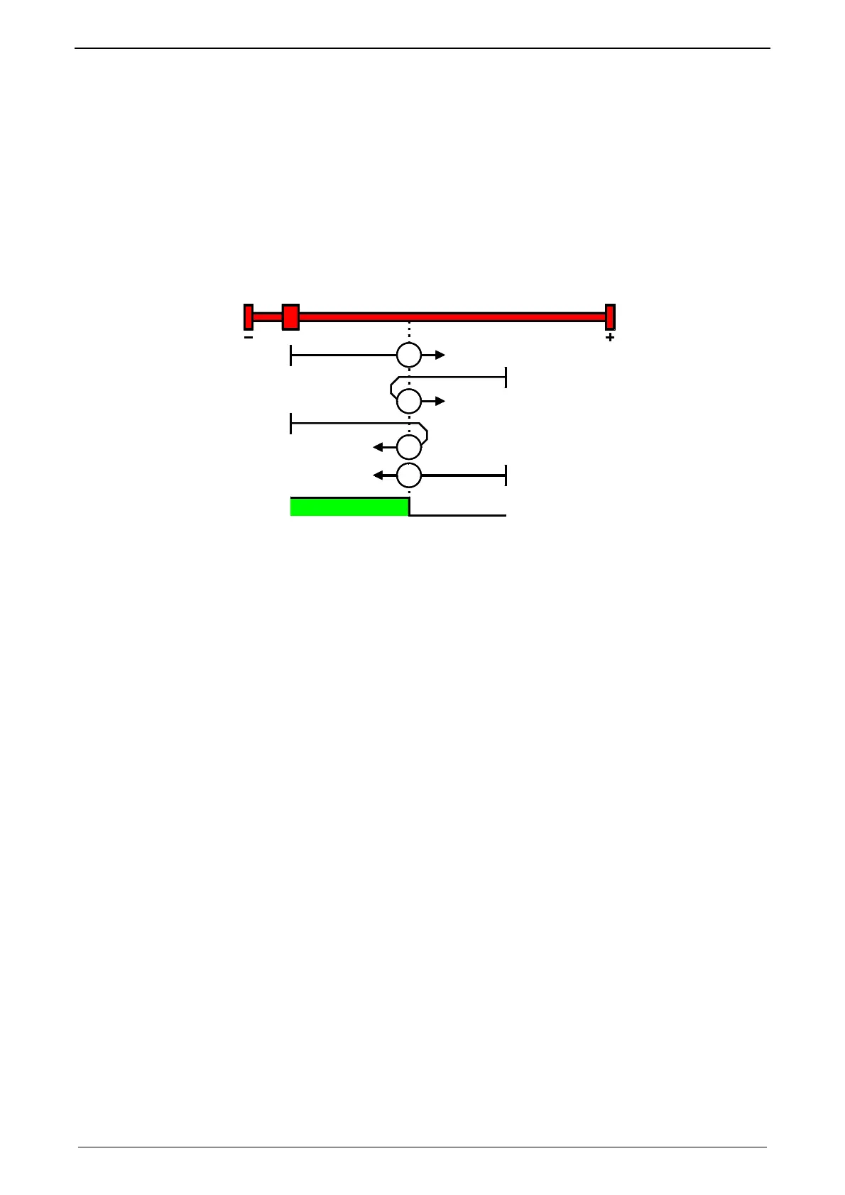
MN-M 21.22: MN initiator = 1 on the negative side
The MN initiator can be positioned at any location within the travel range. The tra-
vel range is then divided into 2 contiguous ranges: one range with deactivated MN
initiator (positive part of the travel range) and one range with activated MN initiator
(negative part of the travel range).
When the MN initiator is inactive (signal = 0) the search for the machine reference
is in the negative travel direction.
MN-M 21:The negative edge of the MN proximity switch is used directly as MN
(home) (the motor zero point remains without consideration).
MN-M 22:The positive edge of the MN proximity switch is used directly as MN
(home) (the motor zero point remains without consideration).
22
22
21
21
1
1: logic state
Without motor zero
point, without direc-
tion reversal swit-
ches

Table of Contents

Other manuals for Parker Compax3 Series

Questions and Answers:

Question and Answer IconNeed help?

Do you have a question about the Parker Compax3 Series and is the answer not in the manual?

Parker Compax3 Series Specifications

General IconGeneral
Enclosure RatingIP20
Control ModesSpeed, Torque, Position
Communication InterfacesCANopen, EtherCAT
Feedback OptionsIncremental Encoder, Resolver
Protection FeaturesOvercurrent, Overvoltage, Undervoltage, Overtemperature, Short Circuit
Cooling MethodForced Air, Natural Convection
Relative Humidity5 to 85 %, non-condensing
Operating Temperature0 to +45 °C (derating may apply above 40°C)

Related product manuals