Parker EME
Compax3 device description
192-120114 N5 C3I22T11 June 2008 41
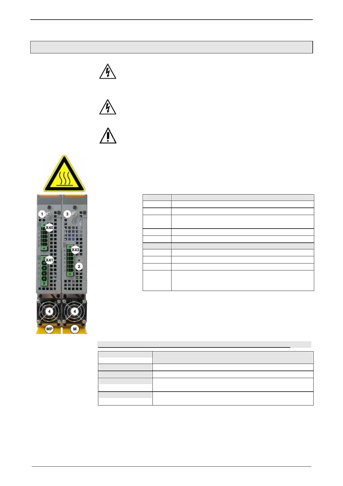
3.5.2. Connections on the device bottom
Always switch devices off before wiring them!
Dangerous voltages are still present until 5 minutes after switching
off the power supply!
Caution!
When the control voltage is missing there is no indication whether or not
high voltage supply is available.
PE connection
The PE connection is made with 10mm
2
via a grounding screw at the bot-
tom of the device.
Attention hot surface!
The heat dissipator can reach very high temperatures (>70°C)
MP Power module
X40 Braking Resistor
X41 Mains supply VAC/PE
1 Central ground connection for the axis combination,
with 10mm
2
to the ground screw on the housing.
4 Fan*
M Axis controller
X43 Motor / Brake
2 Fixing for motor shield clamp
4 Fan*
3 optinally, the axis controller features a ground screw
on the housing, if the grounding is not possible via the
back plate.
* is internally supplied.
Line cross-sections of the power connections (on the device bottoms)
Compax3 device: Cross-section: Minimum... Maximum[mm
2
with contactor slee-
ve]
M050, M100, M150
0,25 ... 4 (AWG: 23 ... 11)
M300
0,5 ... 6 (AWG: 20 ... 10)
MP10
Mains supply: 0,5 ... 6 (AWG: 20 ... 10)
Braking resistor: 0,25 ... 4 (AWG: 23 ... 11)
MP20
Mains supply: 0,5 ... 16 (AWG: 20 ... 6)
Braking resistor: 0,25 ... 4 (AWG: 23 ... 11)

 Loading...


