Parker EME
Setting up Compax3
192-120114 N5 C3I22T11 June 2008 219
lutely not be excluded. Even a system adjusted before, would show an angular
error, for example after a current failure. Therefore the angular error occurring ran-
domly upon each new switching on must always be compensated in an incremental
system.
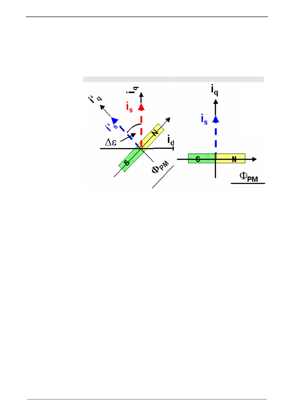
Display of the commutation error in incremental feedback systems
Δε = 0 (adjusted) Δε ≠ 0 (not adjusted)
Rotor was turned in switched-off state.
blue: ideal position
red: unfavourable position
PM: magnetic flux of the permanent magnets
i
S
: Current pointer
Δε
Commutation error
I’: ideal position
i
q
: Quadrature current (torque forming)
The automatic commutation function (AK) in Compax3 uses the position dependent
sinusoidal torque course of permanently excited AC synchronous motors. If the
motor windings are energized with DC voltage for instance, the motor develops a
sinusoidal torque depending on the rotor position, which can be used for example
by evaluating the resulting movement in order to determine the correct motor
commutation.
The automatic commutation with movement in the Compax3 has the following pro-
perties:
The motor movement occurring during the commutation is, with correctly parame-
terized function, very small. It is typically in the range smaller than 10° electrical
revolution (=10°/motor poles physically or 10°/360°*motor pitch for a linear mo-
tor).
The precision of the acquired commutation angle depends on the external condi-
tions, however lies normally in the range better than 5° electrical revolution.
The time until the termination of the commutation acquisition is typically below
10s.

 Loading...


