Setting up Compax3 C3I22T11
280 192-120114 N5 C3I22T11 June 2008
Linear Systems (LTI System)
Further explanations are based on the concept of so-called linear systems. This
means that doubling the input value means that the portion of the output value
influenced by it is also doubled. this, for instance, is not the case in the event of
influence due to limitations, friction and backlash.
=> those are called non-linear systems, which can not be analyzed with the me-
thods described here (or only with difficulties).
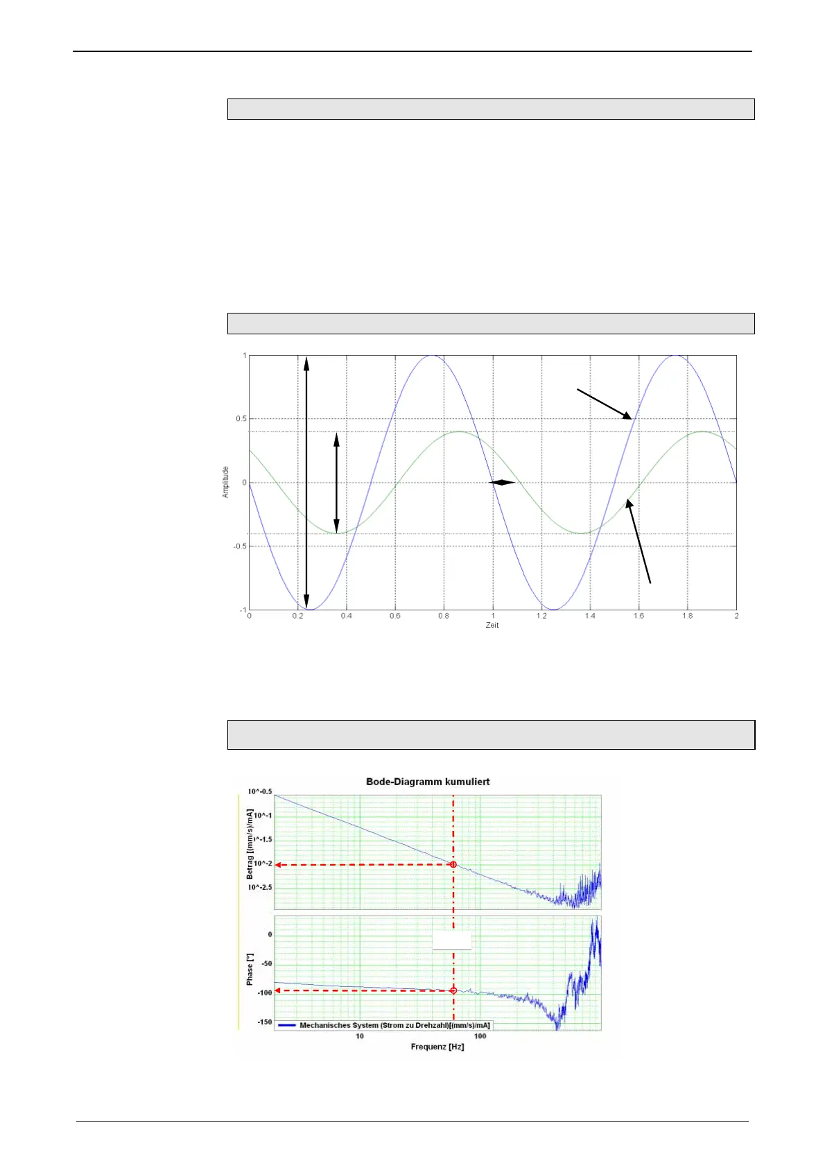
One of the most important properties of linear systems is that a sine signal, which
is put through a linear system, is still a sine signal at the output, which differs from
the input signal only in value and phase.
When a signal passes a LTI system, no new frequencies are generated.
Input and output signals of a linear system
=
*
Input Signal
Output Signal
-
(f0)
A
In
ut
If you know the value (V(f0)) as well as the phase position (u(f0)) for all frequen-
cies, the LTI system is completely defined.
Such a graph of value and phase position in dependance of the frequency, is called
frequency response or bode diagram.
=> only LTI systems can be analyzed with the aid of frequency responses.
Frequency response / bode diagram
10
-
=0.01 [(m/s)/A]
-94°
60Hz

 Loading...


