Parker EME
Setting up Compax3
192-120114 N5 C3I22T11 June 2008 283
The shown system corresponds for instance to a motor with a flywheel coupled via
a shaft. Hereby J1 corresponds to the motor moment of inertia and J2 to the mo-
ment of inertia of the flywheel.
Calculation of the resonance frequencies in the rotary system with a hollow
shaft as elastic coupling element
⎟
⎟
⎠
⎞
⎜
⎜
⎝
⎛
+⋅⋅
⋅
=
21
Re
11
2
1
JJ
Df
s
π
2
Re
2
1
J
D
f
sA
⋅
⋅
=
π
)
l
rrG
drr
l
G
D
IA
r
r
A
I
⋅
−⋅⋅
=⋅⋅
⋅⋅
=
∫
2
2
44
3
ππ
G Shear modulus of the material used [N/m²]
(e.g. approx. 80750N/mm² for steel)
D Torsional rigidity in [m/rad]
rA Outer radius of the hollow shaft
rI Inner radius of the hollow shaft
l Length of the hollow shaft
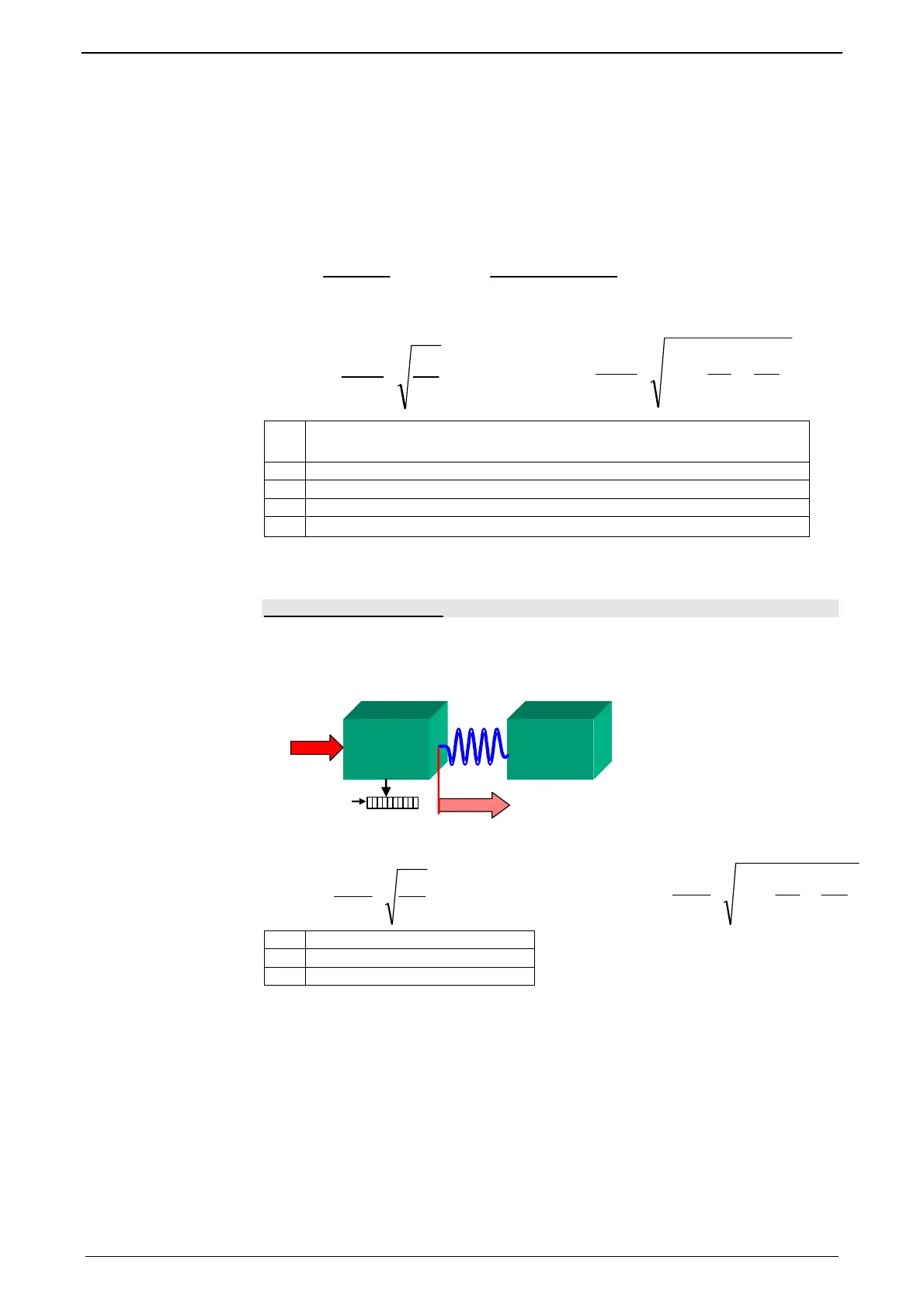
Linear two mass system
M1
M2
F
F
1
1
D
D
F
F
2
2
Feedback
Resonance frequencies in the linear system
⎟
⎟
⎠
⎞
⎜
⎜
⎝
⎛
+⋅⋅
⋅
=
21
Re
11
2
1
mm
Df
s
π
2
Re
2
1
m
D
f
sA
⋅
⋅
=
π
D Rigidity in [N/m]
m1 e.g. motor mass
m2 e.g. load mass

 Loading...


