14
Workshop Manual, TPD 1377E, issue 4 117
100 Series
Alternator Testing Operation 14-3
To avoid the return of parts that are not faulty, follow this procedure for all suspected failures. This will isolate
the problem between either the alternator or the main electrical system.
Check that all connections to the alternator are secure and free from contamination. If the alternator is earthed
using the engine block check that there is a good connection between the alternator, the earth connection and
the engine block. If the alternator mounting bracket is of the black painted type, the bracket should be removed
from the engine block and the paint removed from the mounting surfaces between the alternator, the mounting
bracket and the engine block.
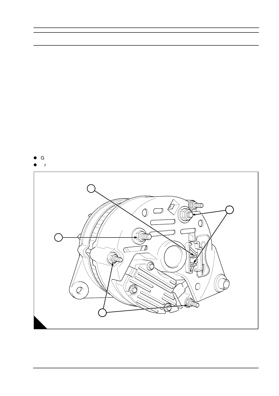
If the machine tachometer is not operating, check the security of the ‘W’ terminal (A3, B3).
If the alternator is excessively contaminated by dust or dirt, use an airline and compressed air applied to the
vent holes on the alternator.
If the ignition warning lamp is illuminated, check the phase wiring (A4, B1).
Check the alternator charging voltage with a volt meter between the alternator +Ve (A1, B2) and the alternator
earth terminal (A2) when the engine is operating at idle, with the minimal electrical load. The voltage should
be between 13.6 and 14.7 volts, if it is outside this range then the alternator is faulty.
Notes:
Graphic A - External fan type.
Graphic B - Internal fan type.
A
K1242
1
4
2
3
This document has been printed from SPI². Not for Resale