2
Workshop Manual, TPD 1377E, issue 4 19
100 Series
Crankshaft deflection
1 Support the crankshaft with a V-block.
2 Position a dial gauge on the crankshaft centre journal, and turn the crankshaft gradually by one full turn.
3 If the gauge reading is more than the service limit correction or replacement of the crankshaft is needed.
4 If measured diameter is less than the service limit, correct by grinding and use undersized bearings and bush.
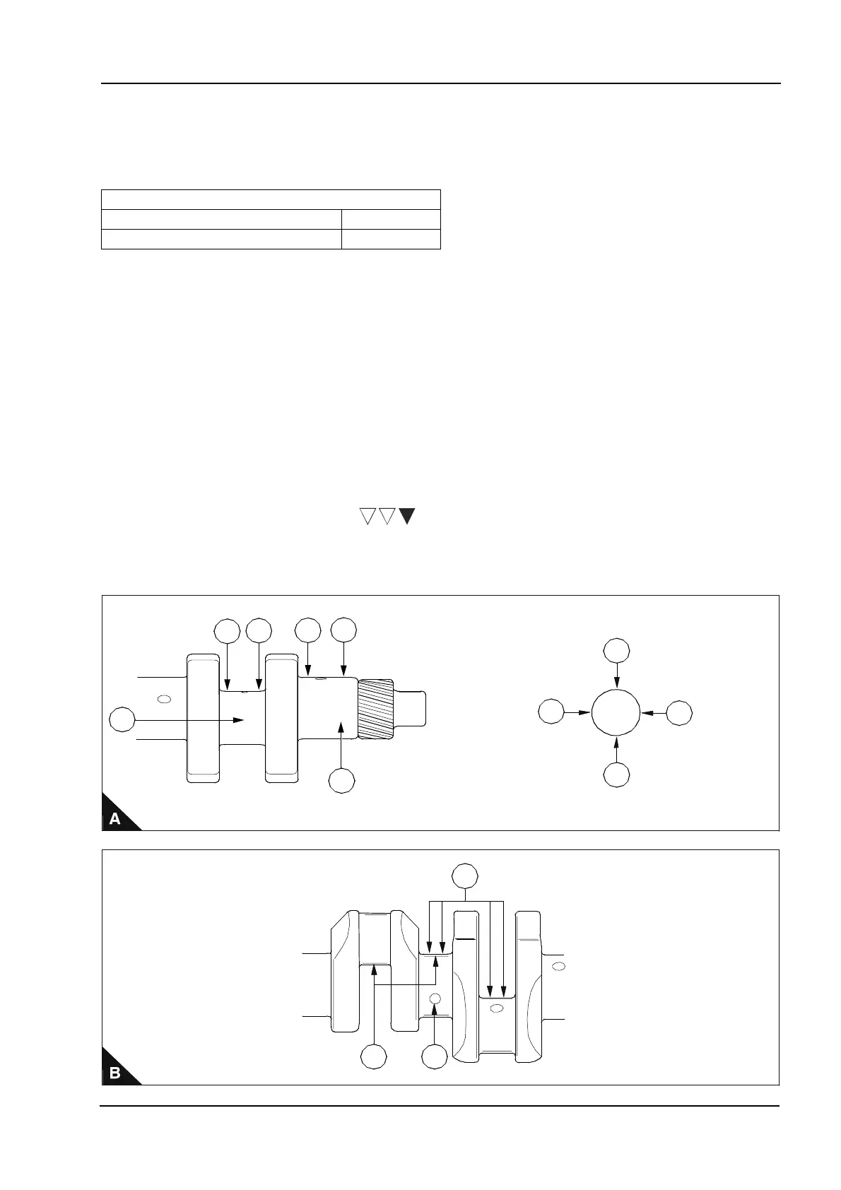
Crankshaft inspection
1 Check the oil seal contact face for damage or wear.
2 Check oil holes for blockage.
3 Check crankshaft journal (A4) and pin (A3) for stepped wear. Take measurements of diameters (A5-A5) and
(A6-A6) at positions (A1) and (A2). If the maximum difference between the measurements (stepped wear) is
more than the service limit of 0,05 mm (0.0019 in) then correction is required.
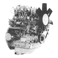
Grinding specification
When grinding the crankshaft, work with the following specifications:
Note: Use No. 400 emery cloth for final polishing.
Deflection mm (in)
Standard Service limit
0,03 or less (0.011) 0,06 (0.0023)
Radius at pin/journal (B1): 3 mm ± 0,2 mm (0.118 in ± 0.0078 in).
Finish precision (B2): 1.6Z
Radius around oil hole (B3): 2 mm (0.0787 in) maximum/5 mm (0.196 in) minimum.
3
4
1
2
1
2
5
5
6
6
1
2 3
This document has been printed from SPI². Not for Resale