14
Workshop Manual, TPD 1377E, issue 4 121
100 Series
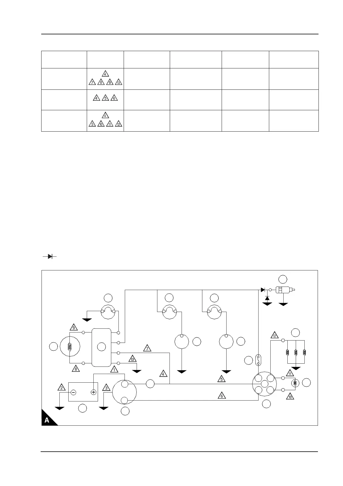
Wiring diagram 14 and 15 amp alternator - 102-05, 103-07, 103-10
Wiring diagram maximum circuit resistance
The resistance of battery cables 1, 2 and 3 must not exceed 0.0018
Ù.
Note: If a glow signal is not used - it is still necessary to connect terminal 19 and 17 on the switch.
(1) Max current draw for standard oil pressure switch is 0.42 amps (5 Watt lamp max).
Circuit Cable number Circuit current
Maximum circuit
resistance
Maximum circuit
volt drop
Remarks
Alternator
charging
14 amp (2 cyl)
15 amp (3 cyl)
0.036 Ù (2 cyl)
0.033 Ù (3 cyl)
0.5 Volt
See Glow Plugs
Circuit
Starter motor
solenoid
15.75 amp 0.04 Ù 0.63 Volt
See Glow Plugs
Circuit
STD glow plugs
(via glow signal)
(Peak max)
26 amp (2 cyl)
39 amp (3 cyl)
0.0192 Ù (2 cyl)
0.0128 Ù (3 cyl)
0.5 Volt
1 Alternator warning lamp
2 Regulator
3 Alternator
4Battery
5 Starter motor
6 Oil pressure warning lamp
7 Oil pressure switch
(1)
8 Water temperature warning lamp
9 Thermostat switch
10 Fuse
11 Key switch
12 Glow signal
13 Glow plugs
14 Solenoid switch
15 A delayed fuse can be fitted if required
= Diode. Capacity: Current 3 amp. Reverse Voltage: 600V. (This is mandatory).
Y
R
B
B
S
AC
17
30
50 19
Sb
Sb
G
2
1
3
4
5
11
12
13
10
6
8
9
7
14
15
This document has been printed from SPI². Not for Resale