5
62 Workshop Manual, TPD 1377E, issue 4
100 Series
Main bearings
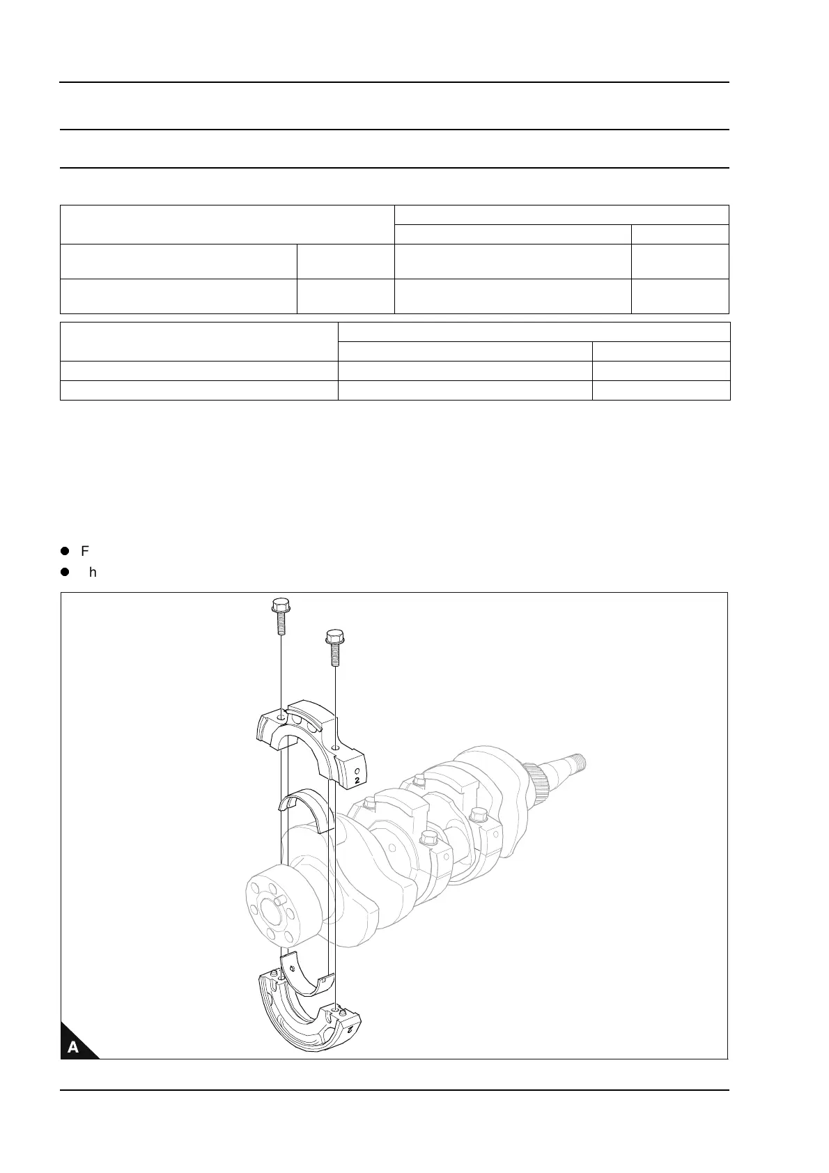
To dismantle and to assemble (two and three cylinder engines) Operation 5-5
Special requirements
1 Identify position of bearing carriers on shaft.
2 Install bearing carriers on the crankshaft ensuring oil holes align with feed holes in cylinder block.
3 Check end float.
4 Check number 2 bearing holder on 102-05 engines and number 3 bearing holder on 103-07 and 103-10
engines for wear, poor contact, look burnt or other defects. Defective bearing holders must be renewed.
Notes:
For emissions approved engines. The fuel adjustment screw must not be altered from the original setting.
The maximum No Load Speed must be checked after assembly.
Torque Nm (lbf ft) kgf m
Bearing holder (Aluminium) : Thickness mm (in)
Standard Service limit
102-05, 103-07, 103-10
Aluminium Bearings
22 (16) 2,2 21,85 - 21,95 (0.8602 - 0.8641) 21,6 (0.8503)
102-05, 103-07, 103-10
Cast Iron Bearings
27 (19.9) 2,7 N/A N/A
Engine model
End Float : Clearance mm (in)
Standard Service limit
102-05, 103-07 0,10 - 0,30 (0.0040 - 0.0120) 0,50 (0.0197)
103-10 0,05 - 0,30 (0.0020 - 0.0120) 0,50 (0.0197)
This document has been printed from SPI². Not for Resale