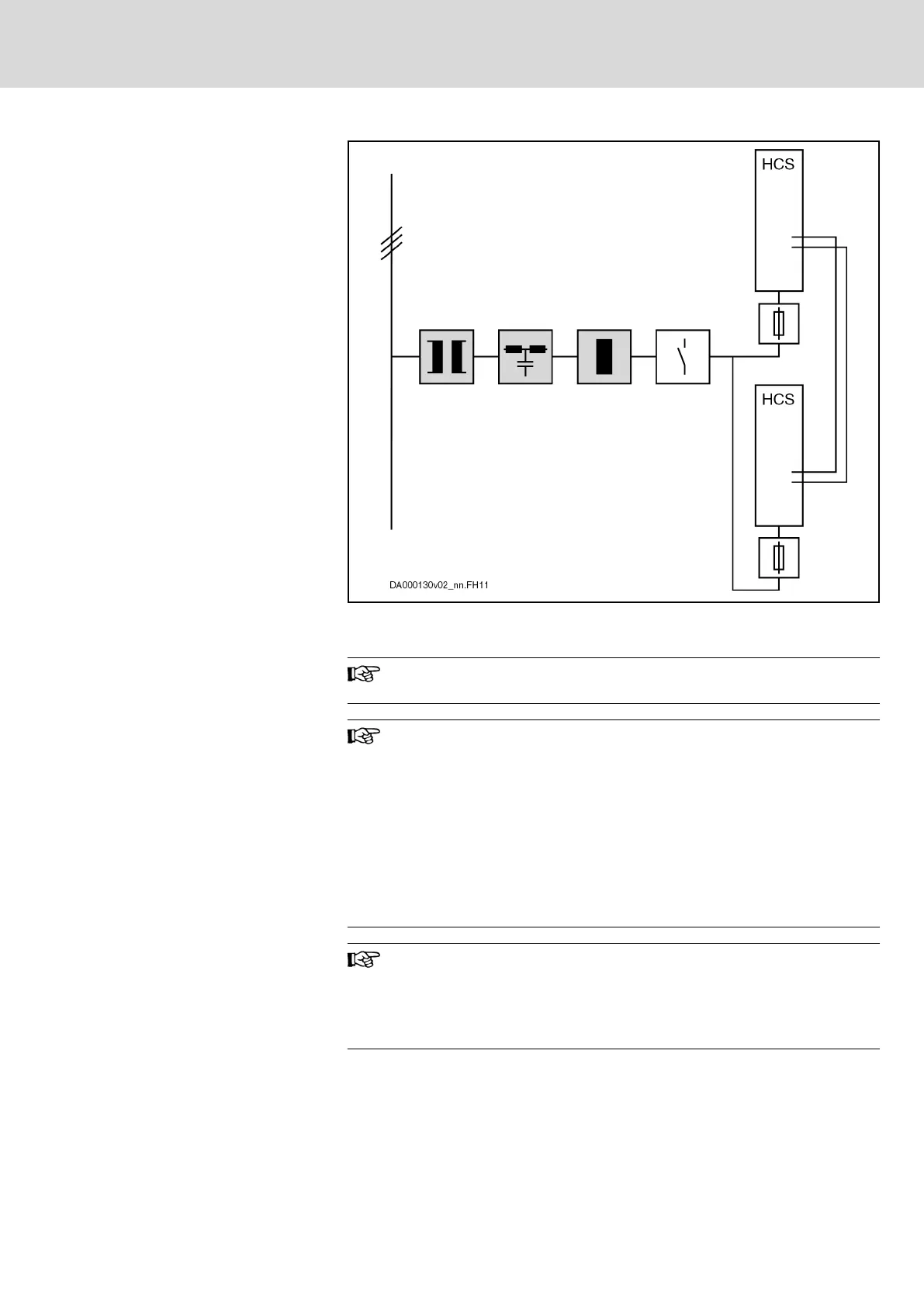
Block Diagram
Components marked with gray background color: Optional, depending
on the application
Fig.8-6: Parallel Operation HCS
Notes on Project Planning
Parallel operation is only allowed with drive controllers of the
same type current.
Mains contactor
When using the component HCS03.1E with HNK01.1, connect
the mains contactor electrically before HNK and HCS03.
Control mains contactors in such a way that error messages at
the converters connected in parallel can interrupt the power sup‐
ply from the mains (e.g., connect Bb contacts of HCS in series).
When controlling several mains contactors, additionally make
sure that the mains contactors are always controlled simultane‐
ously and synchronously so that each HCS only has to charge its
own DC bus capacitors when power voltage is switched on.
When dimensioning the fuses in the supply feeder and in branch‐
es, make sure to provide protection against overcurrent and over‐
load in the case of error.
See chapter 15.3.5 "Dimensioning the Line Cross Sections and
Fuses " on page 266
DOK-INDRV*-SYSTEM*****-PR06-EN-P
Rexroth IndraDrive Drive Systems with HMV01/02 HMS01/02, HMD01, HCS02/03
Bosch Rexroth AG 103/309
Configuring the Drive System