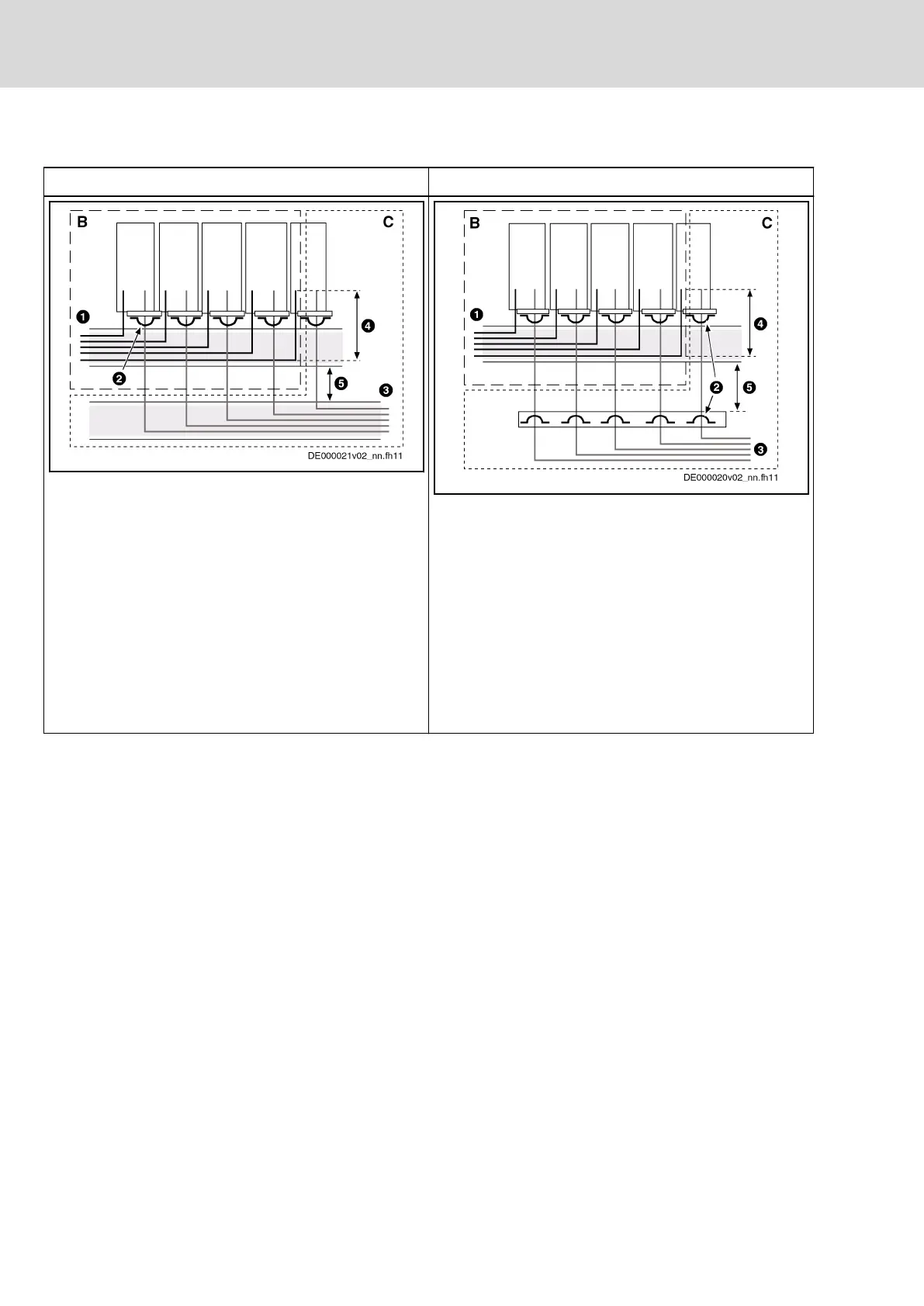
Converter - Routing the Motor Power Cables
With cable duct Without cable duct
B Area B
C Area C
1 Cable duct for mains connection lines
2 Shield connection of motor power cable via
clips at least at one point; alternatively, at
the device or on mounting plate at control
cabinet
3 Cable duct for motor power cables
4 Parallel routing of mains connection lines
and motor power cables over a maximum of
300 mm
5 Distance of at least 100 mm or separated by
a grounded distance plate
Fig.11-9: Routing of Motor Power Cables With Cable
Duct
B Area B
C Area C
1 Cable duct for mains connection lines
2 Shield connection of motor power cable via
clips at least at one point; alternatively, at
the device or on mounting plate at control
cabinet
3 Control cabinet outlet of motor power cables
4 Parallel routing of mains connection lines
and motor power cables over a maximum of
300 mm
5 Distance of at least 100 mm or separated by
a grounded distance plate
Fig.11-10: Routing of Motor Power Cables Without Ca‐
ble Duct
Tab.11-7: Routing of Cables for Converter
Bosch Rexroth AG DOK-INDRV*-SYSTEM*****-PR06-EN-P
Rexroth IndraDrive Drive Systems with HMV01/02 HMS01/02, HMD01, HCS02/03
210/309
Arranging the Components in the Control Cabinet