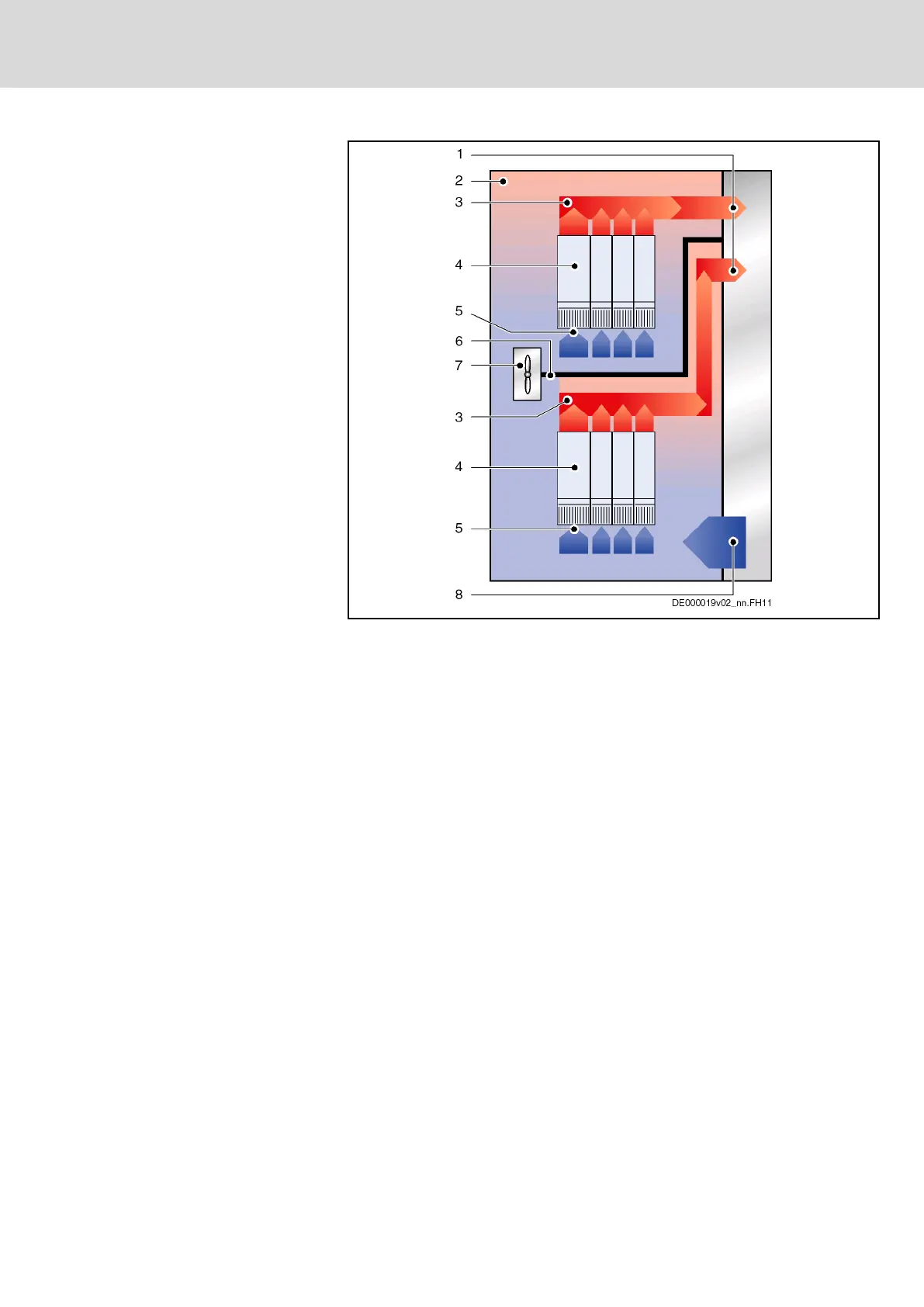
1 Discharge of heated air to cooling unit
2 Interior of control cabinet
3 Conveying direction of heated air in area where air flows off
4 Device in control cabinet
5 Air intake at device
6 Air guide in control cabinet (for liquid cooling, this is also the drip pro‐
tection for the devices beneath)
7 Fan in control cabinet
8 Supply of cooled air from cooling unit
Fig.12-2: Example of Arrangement for Double-Line Design
DOK-INDRV*-SYSTEM*****-PR06-EN-P
Rexroth IndraDrive Drive Systems with HMV01/02 HMS01/02, HMD01, HCS02/03
Bosch Rexroth AG 219/309
Project Planning of Cooling System