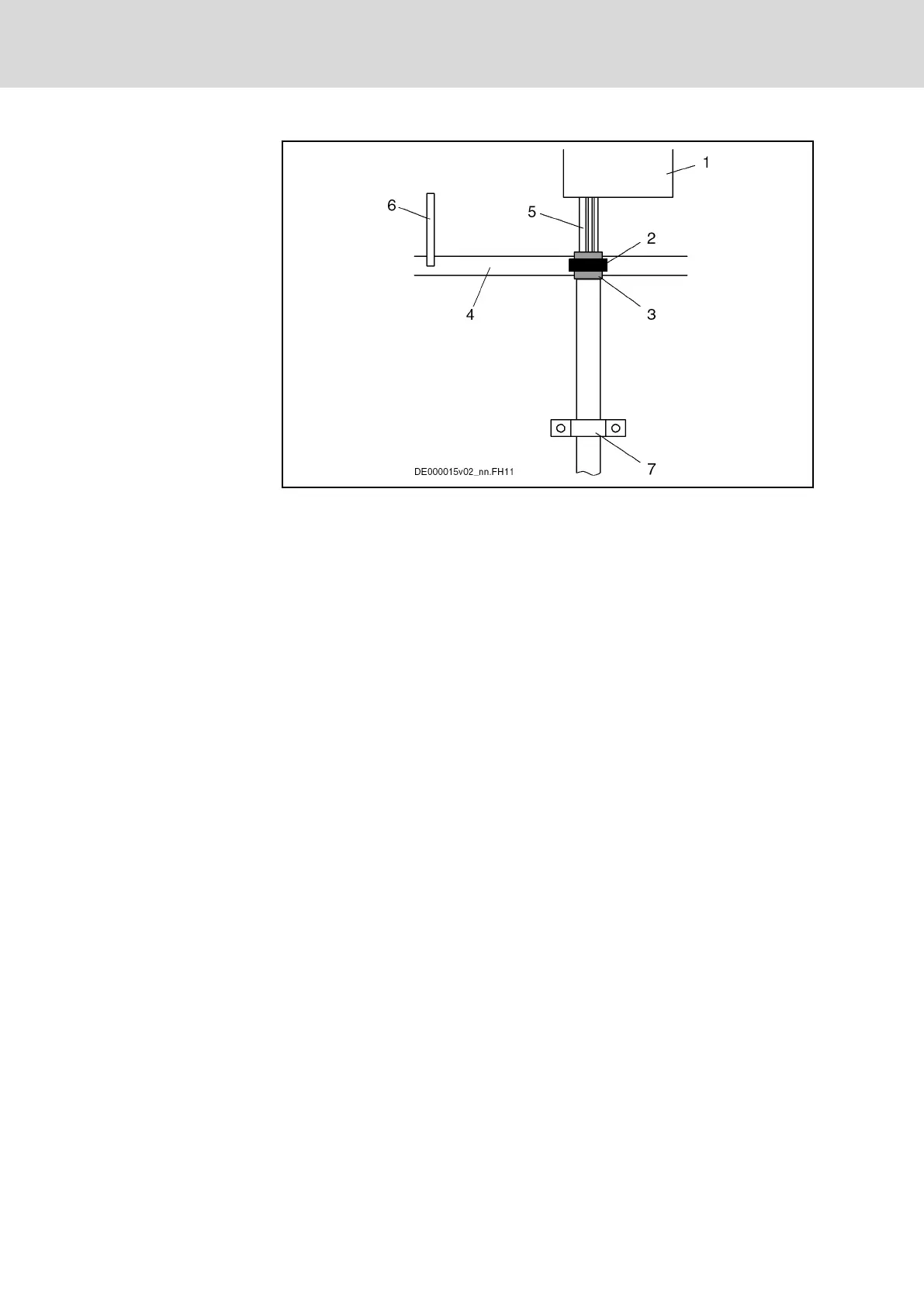
1 Drive controller
2 Clip for shield contact
3 Overall shield of the motor power cable folded back
4 Ground bus in control cabinet
5 Single strands of motor power cable
6 Connection of ground bus to supplying device
7 Strain relief (as near as possible to exit point from control cabinet)
Fig.13-16: Shield Connection, Alternative 1
● With a clip (2), connect overall shield of motor power cable (3) to ground
bus (4). (If you use your own cable, make sure the shields of the two in‐
ner pairs of wires are in contact with the overall shield.)
● With a cable (6) (line cross section: at least 10 mm
2
), connect ground
bus (4) to ground connection at supplying device (Rexroth IndraDrive
supply unit or Rexroth IndraDrive drive controller HCS).
Alternative 2
Connect cable shield to a ground bus. The cable length between device and
ground bus mustn't be more than a maximum of 1 m. For this purpose, pre‐
pare the motor cable in accordance with the description below:
Bosch Rexroth AG DOK-INDRV*-SYSTEM*****-PR06-EN-P
Rexroth IndraDrive Drive Systems with HMV01/02 HMS01/02, HMD01, HCS02/03
238/309
Connections of the Components in the Drive System