For the data of the TPF, see Project Planning Manual "Rexroth
IndraDrive Supply Units and Power Sections" → Chapter of the re‐
spective device → "Technical Data" → "Basic Data" → table "Data
for Mains Voltage Supply".
Maximum Allowed Connected
Load at the Mains
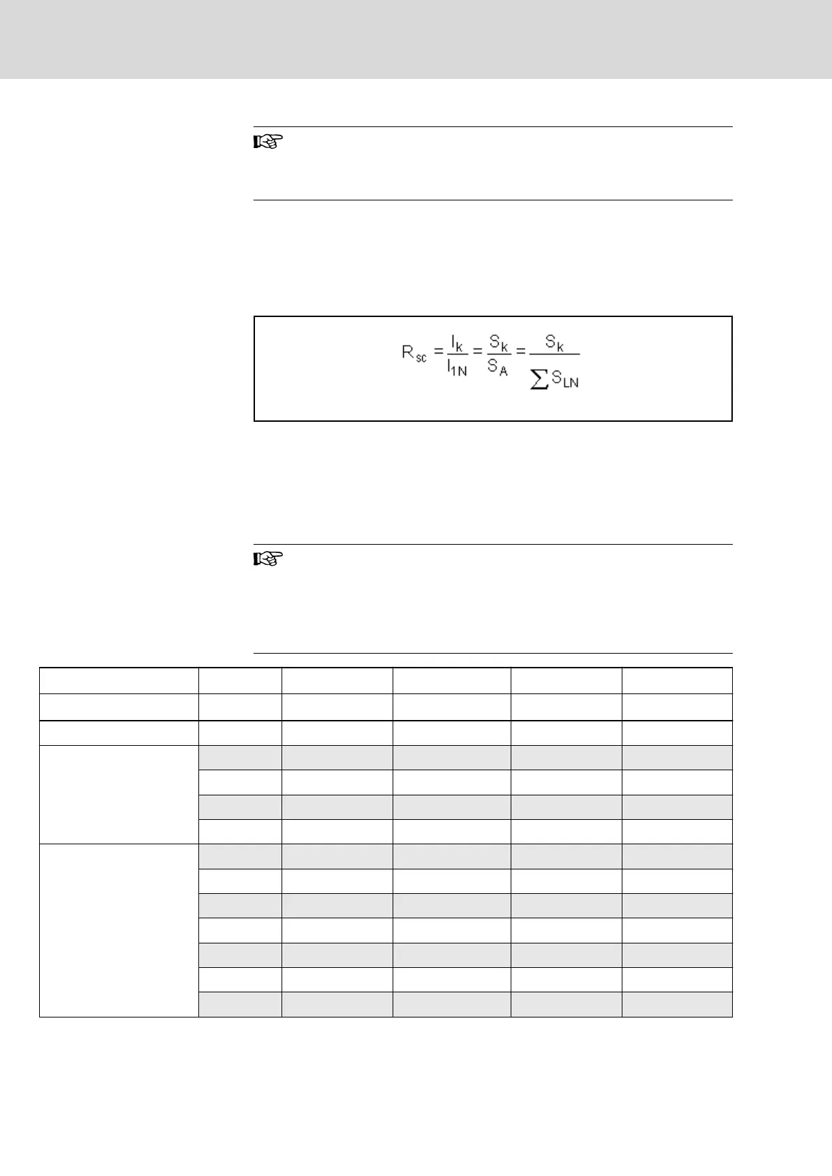
The maximum allowed connected load at the mains depends on the allowed
distortion of the mains voltage due to the load current with harmonics (mains
pollution). The distortion is described by the total harmonic distortion (THD) of
the mains current (siehe chapter 15 "Calculations" on page 247).
In order to limit the distortion of the mains voltage, take the mains short-cir‐
cuit ratio R
SC
(ratio of the source) into account:
I
k
Mains short-circuit current
I
1N
Fundamental wave of nominal current of all loads at connection point
S
k
Mains Short-Circuit Power
S
A
Connected load of all electric loads at connection point (apparent
power of fundamental wave)
ΣS
LN
Sum of mains connected loads of the supply units or converters
Fig.7-10: Mains Short-Circuit Ratio
The following table is used for first estimation of the maximum al‐
lowed connected load S
A
at the point of power supply connection
in low-voltage mains at known mains short-circuit power S
K
. The
table does not replace the described procedure "Selecting Mains
Connection Components" (siehe "Selecting Mains Connection
Components" on page 84).
R
SC
= 250 R
SC
= 200 R
SC
= 100 R
SC
= 50
Classification
S
k
S
A
S
A
S
A
S
A
MVA kVA kVA kVA kVA
1
Rigid mains
200 800 1000 2000 4000
150 600 750 1500 3000
100 400 500 1000 2000
50 200 250 500 1000
2
Semi-rigid mains
40 160 200 400 800
30 120 150 300 600
20 80 100 200 400
15 60 75 150 300
10 40 50 100 200
5 20 25 50 100
4 16 20 40 80
Bosch Rexroth AG DOK-INDRV*-SYSTEM*****-PR06-EN-P
Rexroth IndraDrive Drive Systems with HMV01/02 HMS01/02, HMD01, HCS02/03
82/309
Project Planning of Mains Connection