Because RFL™ and Hubbell® have a policy of continuous product improvement, we reserve the right to change designs and specifications without notice.
RFL VF-10D RFL Electronics Inc.
June 23, 2001 13 (973) 334-3100
Notes for Table 3:
1. The maximum analog level for transmit and receive is 0dBm. The TX Input Level may be increased to a value greater
t
han 0dBm to provide additional offset attenuation. The RX Input Level may be increased to a value greater than
0dBm to provide additional offset gain.
2. This switch position can be used to set 0.5 dB in
crements. See paragraph 7 on page 7 for details.
3. Factory default.
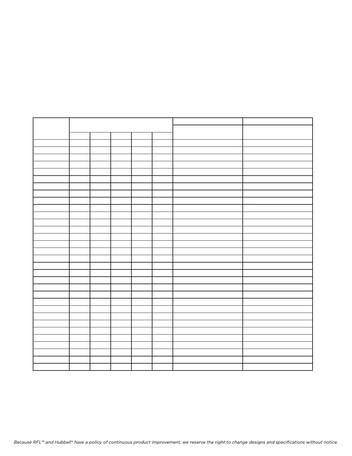
Table 4. Time Slot Select for RFL VF-10D module.
Switch T1 E1
Code Channel 1 Channel 1
(Decimal) 1 2 3 4 5 Time Slot Time Slot
0 D D D D D * *
1 D D D D U 1 1
2 D D D U D 2 2
3 D D D U U 3 3
4 D D U D D 4 4
5 D D U D U 5 5
6 D D U U D 6 6
7 D D U U U 7 7
8 D U D D D 8 8
9 D U D D U 9 9
10 D U D U D 10 10
11 D U D U U 11 11
12 D U U D D 12 12
13 D U U D U 13 13
14 D U U U D 14 14
15 D U U U U 15 15
16 U D D D D 16 *
17 U D D D U 17 17
18 U D D U D 18 18
19 U D D U U 19 19
20 U D U D D 20 20
21 U D U D U 21 21
22 U D U U D 22 22
23 U D U U U 23 23
24 U U D D D 24 24
25 U U D D U * 25
26 U U D U D * 26
27 U U D U U * 27
28 U U U D D * 28
29 U U U D U * 29
30 U U U U D * 30
31 U U U U U * 31
Notes: * This setting is not allowed . Setting switches to this code will cause the module’s service to be disabled.
D = down, U = up.