FX-20
8.2 CONTROL INPUT / SWITCH SELECTION MENU
The FX-20 software contains a comprehensive control input
selection menu. Virtually all functions can be allocated to any
control input. It doesn’t matter whether they are for a switched
or proportional control or a flight condition. The appearance of
the selection menu is always the same.
As soon as a function is selected and confirmed with “RTN”,
the following Hardware Selection (H/W SELECT) menu will ap-
pear. Please note that this menu differs somewhat from func-
tion to function, according to the application, the display and
selection changes according to the selected application. The
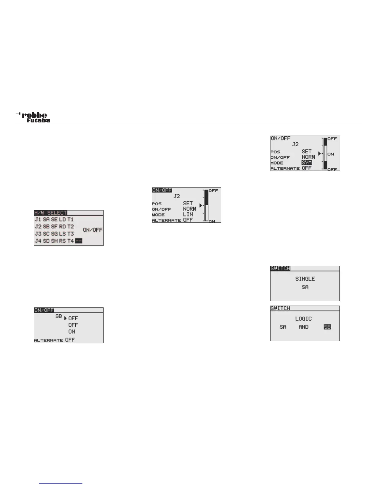
example shows the switch selection menu for the “program-
mable mixer” function. All relevant controls, switches and trim
buttons are active and displayed.
J1...J4 = Control stick axes 1...4
SA...SH = Switches A...H
LD...RD = Left/Right hand rotary knobs
LS...RS = Left/Right hand linear sliders
ON/OFF = Switch position selection
T1...T4 = Digital Trim levers
SI...SJ = optional stick switches
Highlight the required switch or controls and confirm with the
‘RTN’ key. After a switch has been selected, move the cursor
to the “ON/OFF” field and define the switch position.
A sub menu will appear to confirm the switch position, the ex-
ample shows the switch, ‘SB’.
If a control stick or proportional control were selected, more
functions can be adjusted in the following display.
SET
To set the switch position, move the desired switch to the re-
quired position and move the cursor to SET and press “RTN”
key. The switch point is now indicated on the displayed bar
chart.
ON / OFF
This menu defines the switch direction sense, „NORM“ Normal
or „REV“ reverse direction.
MODE:
LINEAR
This setting divides the control area into separate ON and OFF
zones (see above bar chart graphic). Dependent on the control
position, the function is switched on and off.
SYMMETRICAL
Both switch points are symmetrically positioned about the con-
trol centre position. A switch position will be created as soon
as the control value exceeds the upper or lower limit values.
MEMORY
In the lower section of the display, the switch style key (OFF)
or (ON), are defined.
Exemple:
Taster aus Ruhestellung einmal in die getastet Position und
wieder zurück in die Ruhestellung bringen = Funktion einge-
schaltet.
Taster nochmals in die getastet Position und wieder in Ruhe-
stellung bringen = Funktion ausgeschaltet.
LOGIC-FUNCTIONS
Certain functions, such as flight condition can be also opera-
ted/switched with a logical cascade of two switches; this is the
so-called Logic-Function.
Select switch MODE (SINGLE) or with a logical coupling
(LOGIC).
Here are the following functions available:
• AND: Serial coupling of two switches
E.g. „SA AND „SB“ activate a function.
• OR: Parallel coupling of two switches
E.g. „SA“ OR „SB“ activates the function.
• EX-OR: EITHER -OR coupling or exclusion of defined swit-
ches. E.g. EITHER „SA“ OR „SB“ will activate the
function.
17
Switch selection