FX-20
12.1 FUNCTION
The selection of the Model Type acts as the basis for the Mix
functions and Control assignment and automatically defines
the Control Configuration for a selected Model Type. All servo
outputs channels, functions (aileron elevator etc) and control
(sticks, switches and trim levers) are freely assignable. Howe-
ver, we recommend, wherever possible, to keep the standard
control allocation layout to be able to maintain a consistent
control standard.
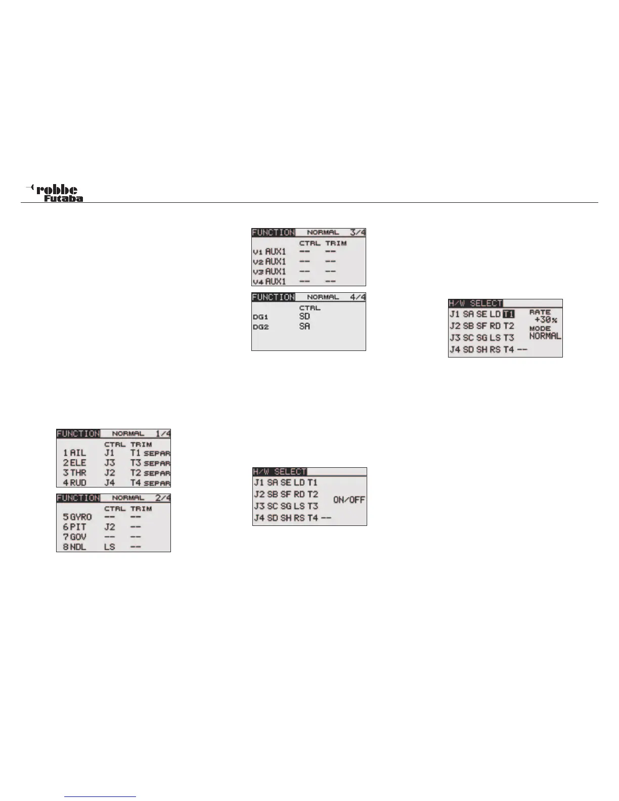
In the “FUNCTION” menu, there is a summary display of which
servo is connected to its respective receiver output. On func-
tions with two or more servos, the corresponding control that
is configured in the software is also displayed. Within a Model
Type, the control configuration varies very little.
CHANGING FUNCTIONS
Highlight the “FUNCTION” Menu in the Linkage Menu using the
“CAP TOUCH SENSOR“ and confirm with “RTN”. There are 4
pages in the function menu, the page number is found in the
right hand part pf the Display. This menu allows you to assign
the Transmitter control, trim and the receiver output channel for
all control functions.
The following Displays look like:
Every control function can be assigned to a preferred
transmitter control. Likewise, the corresponding channel
can also be freely modified.
• To do this, highlight “FUNCTION” with the “CAP TOUCH
SENSOR” and confirm with “RTN”
• Then scroll to the respective function, e.g. ‘TAIL’ for tail-
rotor.
• Finally, assign the required control for this function. High-
light the selected channel in ‘CTRL’ column and activate.
The Display changes to H/W SELECT Menu which shows a
symbolic table of all the transmitter controls.
• The required control can now be selected for the chosen
Function in this menu by scrolling the flashing cursor with
the “CAP TOUCH SENSOR“ and confirm the assignment
by touching the ‘RTN’-key.
SELECT TRIM LEVERS
The trim levers are also freely assignable. The method is iden-
tical to the Control assignment. Highlight and confirm the func-
tion in the Trim column, the Trim Control Menu will appear in
the H/W SELECT Menu. The selected Trim may be assigned
to any of the Controls in the table on the left hand side of the
menu.
TRIM SETTINGS
This Menu allows the following further settings to be made:
• Trim Rate
The setting of the Trim Rate range is from -150 to +150%
of the control throw. The Initial value is +30%. Following
the highlighting and activation of this option, scroll the ‘CAP
TOUCH SENSOR’ to adjust the %-value. Confirm by tou-
ching the ‘RTN’-key for 1 second will reset it to the initial
value (30%).
• Trim Mode
Following the highlighting and activation of this option,
scroll the ‘CAP TOUCH SENSOR’ to assign the following
Trim Modes
NORM = Normal Mode, the Trim range is symmetrical about
the middle. The selected Trim range will be moved about the
middle, which also moves the servo End Point accordingly.
ATL = Asymmetrical Trim Limit, changes the Trim range at
only one end of the servo travel, used mainly for idle trim ad-
justment without affecting the full throttle position.
ATL Normal/Reverse= Trim operation operates either above
(Normal) or only below (Reverse) the neutral stick position.
Linkage menu helicopter
49