FX-20
83
16. Tips for the installation of 2.4 GHz receivers and
aerials
Over the years, RC users gather their own experience in the
installation and use of RC components. 2.4 GHz technology
has ushered in a new epoch, which brings enormous advan-
tages. At the same time this new equipment is different in
nature from previous technology, and we need to adopt appro-
priate measures when installing and operating a 2.4 GHz
system.
One of the most common mistakes is to wrap the receiver in
foam or fit it in a foam tube as we have always done with 35
MHz receivers, in order to protect the unit from vibration. This
is not necessary with 2.4 GHz FASST receivers, as they do
not contain ceramic filters, and are therefore not vulnerable
to vibration in the same way. This “well meant” measure is
actually counter-productive, as 2.4 GHz receivers contain
high-performance ICs with a fairly high current drain, and
this results in heat generation. Wrapping the receiver in foam
prevents waste heat being dissipated from the receiver. We
recommend that you install 2.4 GHz receivers using double-
sided foam tape (or Velcro tape). If possible the tape moun-
ting should not cover the full area of the case; it is better to fit
tape “feet”, so that air can circulate freely around and under
the receiver. Installing the receiver vertically also enhances
air circulation. The temperature range for radio control system
components is generally stated as -15°C ... +55°C: this is the
typical range, which is stated by manufacturers of electronic
components. This temperature range applies to virtually all
electronic apparatus used in our daily lives.
The same range (-15 ... +55°C) also applies to RC system
receivers, has done for many years, and is equally appli-
cable to the new generation of 2.4 GHz FASST receivers. For
other 2.4 GHz systems this temperature range is significant
because they employ ICs developed for WLAN applications;
these are generally operated under normal conditions, and
their temperature limits are therefore the same. Of course,
the stated maximum is a theoretical ‘safe’ limit, and in practice
these receivers can cope with considerably higher ambient
temperatures (approx. 70 - 75°C). Nevertheless, manufactu-
ring tolerances mean that the component manufacturers can-
not guarantee higher values.
For these reasons we recommend that you handle your 2.4
GHz equipment with appropriate caution, and in particular
observe the following points:
• The use of two LiPo cells without voltage reduction is not
recommended.
• Voltage converters used with LiPo cells generate their own
waste heat, and should not be positioned in the same com-
partment as the receiver, or too close to it.
• On hot, sunny days you should not leave models in the car,
to avoid the model and electronics becoming too hot.
• Provide effective ventilation, or - even better - take the
model out of the car, and park it in the shade of the vehicle.
• If your model is fitted with a clear canopy, or one painted a
light colour, the sun shining through the canopy can heat up
the fuselage and RC components. You can avoid this pro-
blem by removing the canopy to ensure good air circulation
in the fuselage, or by covering the area with a light-coloured
cloth.
• Cover dark-coloured models with a cloth, or park them in
Never leave slim / black CFRP / GRP fuselages containing
a receiver in the car or in bright sunlight.
• Do not install the receiver close to a motor and / or exhaust
system, as the radiated heat may cause the receiver to
overheat.
• Silencers installed inside fuselages should be partitioned
off using balsa panels or similar to avoid heat transfer and
prevent excessive temperatures in the fuselage.
• Take measures to ensure that air can circulate through the
fuselage.
• You may wish to cut ventilation openings in the canopy or
fuselage.
Supplementary notes regarding additional RC components.
Although receivers are a special case, most other electronic
components will also benefit from the measures suggested
above.
• Speed controller heat-sinks, which are already warm or hot,
are not so efficient at dissipating heat, and this may result in
components overheating in use.
• At temperatures of about 45°C and above, LiPo batteries
have a much worse energy yield (approx. 10 - 12%), which
in turn will have an adverse effect on your model’s perfor-
mance.
• Servos also lose a proportion of their power when hot: the
higher the temperature of the motor winding, the worse its
efficiency. This means that the power of a servo may be
reduced by up to 20% at temperatures of 55°C and above
compared with cold conditions. This figure is quickly rea-
ched, as servo motors generate their own heat.
General information on the subject of 2.4 GHz RC systems
• In general terms the range of 2.4 GHz FASST systems is
greater than that of 35 MHz equipment. Close to the ground
the range is around 2000 metres, and in the air it is more
than 3000 metres. The potential range reductions descri-
bed in the following section, caused by unfavourable wea-
ther conditions and obstacles, have no adverse effect on
the system’s function; all they do is reduce the safety mar-
gin.
• Large obstacles between the transmitter and the receiver
can have a damping or blocking effect on the signal.
• Close to the ground the transmitter signal is damped more
severely than is the case with 35 MHz systems. On foggy
days and / or when the ground is wet the range may be
reduced at very low altitudes If a model is close to the
ground, and if an obstacle (person, vehicle, object etc.)
moves between the transmitter and the receiver, then effec-
tive range may be significantly reduced.
• 2.4 GHz signals radiate from the transmitter virtually in a
straight line, for which reason it is essential to maintain
visual contact with the model at all times.
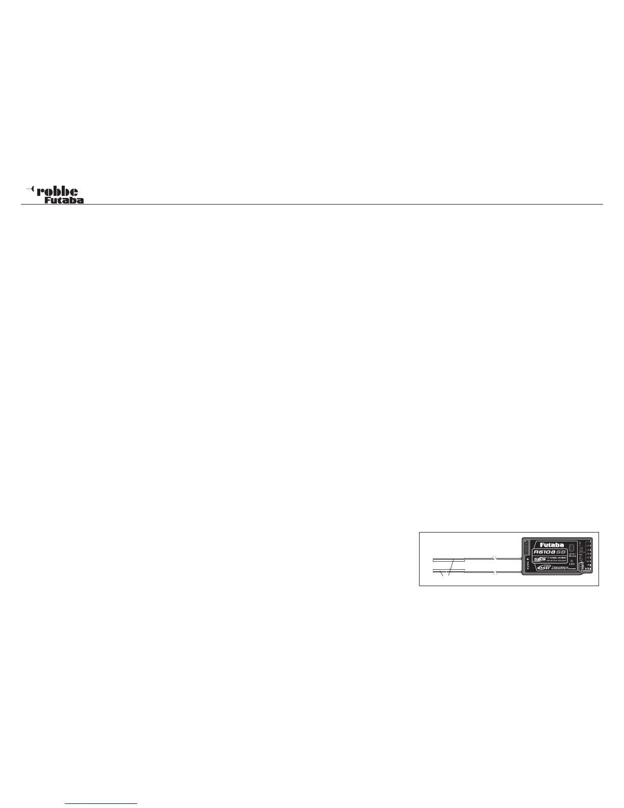
• The FASST R R607, R617, R608, R6008 and R6014 recei-
vers feature a diversity system with dual aerials and corre-
sponding input stages. This system constantly checks the
signal level at both aerial inputs, and switches lightning-fast
to the stronger signal, without any interruption.
• Arranging the two aerials at an angle of 90° to each other
significantly improves the attitude-dependency, which is
usual with a single aerial, and this in turn provides a clear
improvement security of reception.
• The PRE-VISION software constantly scans the input
signal, and carries out error-correction as and when neces-
sary.
To obtain optimum reception results, please note the following
points regarding aerial deployment:
• The two aerials should be deployed in a straight line.
• The angle between the two aerials should be approximately
90°.
• Large models often contain quite large metal parts, which