may have a damping effect on RF reception; in such cases
the aerials, should be positioned to left and right of the
offending object.
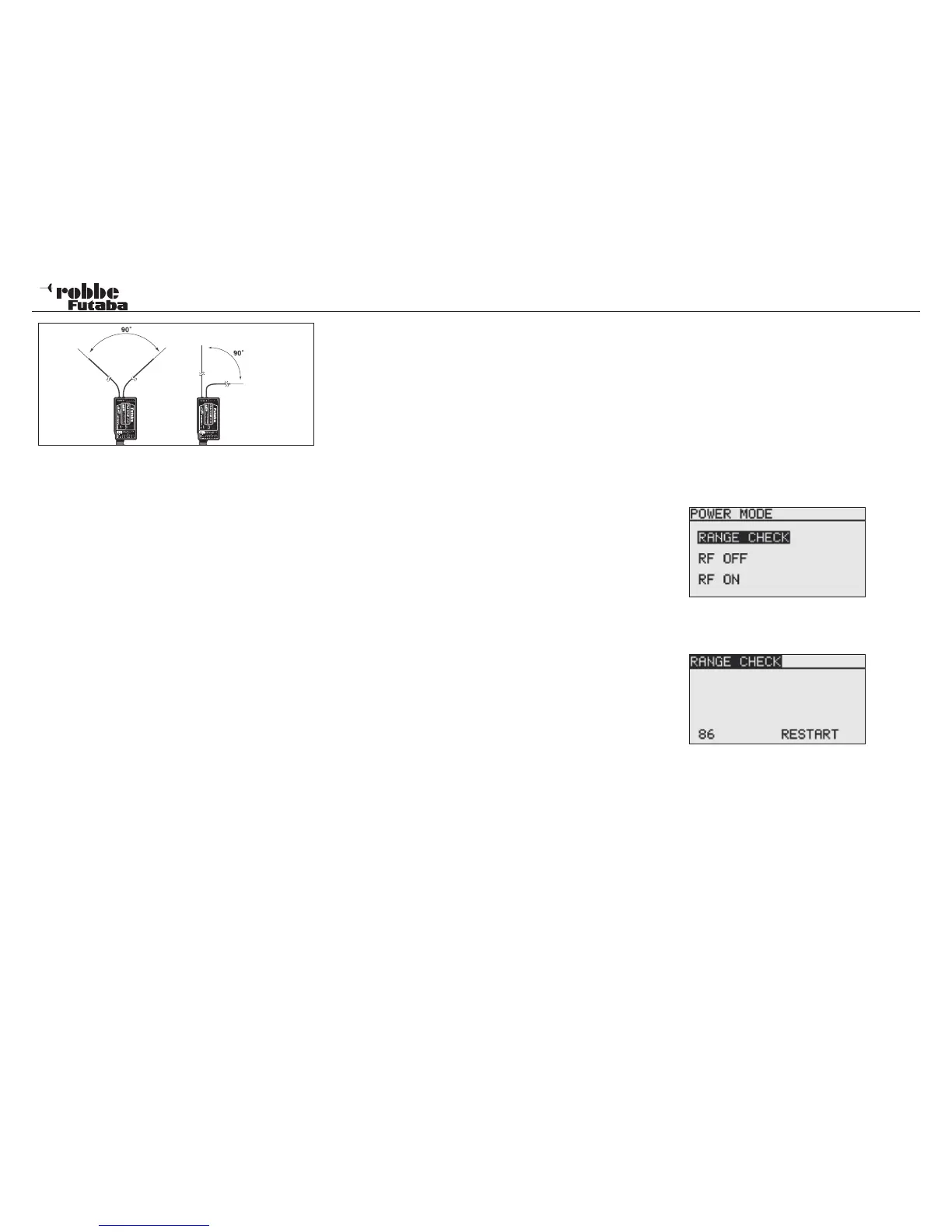
• The aerials should not be deployed parallel with each other,
and should always be positioned at least 1.5 to 2 cm away
from the following items:
• Anything made of metal or carbon, electrical cables, con-
trol ‘snakes’, control cables, carbon fibre pushrods, carbon
roving reinforcements, etc.
• High-current speed controller cables and motor leads;
• Sparkplugs, glowplugs, glowplug heating circuits;
• Locations liable to static charge build-up, e.g. toothed belts,
turbines etc.
• Where the fuselage includes materials with a shielding
effect (carbon, metal, etc.), route the aerials out of the fuse-
lage by the shortest possible route.
• The aerial ends should never be attached to electrically
conductive materials (metal, carbon) either inside or out-
side the model.
• This applies not only to the co-ax cable but also to the end
part of the aerials.
• Avoid bending the co-axial cables through tight radii, and
do not kink the leads.
• Protect the receiver from damp at all times.
Notes on installing 2.4 GHz FASST receivers:
• Wherever possible, the receiver should be powered by con-
sisting of low-impedance NC or NiMH cells.
• Pulsed BEC systems used as receiver power supplies
must be adequately specified; if the voltage under load
falls below 3.8 Volts, then the receiver will carry out a reset
and restart, which equates to a period of signal loss lasting
about two or three seconds. This can be prevented by using
so-called RX capacitors at the receiver, which bridge brief
voltage collapses (RX capacitor, 1800 uF, No. F 1621 or
22.000 uF, No. F 1622).
• FASST 2.4 GHz receivers are relatively immune to ‘elec-
tro-smog’ (such as metal-to-metal noise, stray RF signals,
FX-20
static charge effects, etc.) due to their high intermediate fre-
quency of 800 MHz. At frequencies of about 300 - 400 MHz
and higher the amplitude of these effects is quite small.
Certain supplementary electronic devices are known to be
powerful sources of interference, and under unfavourable
circumstances it may be necessary to install a suppressor
filter, No. F 1413, in order to keep such interference from
the receiver. A range check will show up whether this type
of filter is actually required or not.
To prevent the build-up of powerful static charges certain
measures are required at the model:
Helicopters:
• Use an earthing strap to connect the tail boom to the chas-
sis. Toothed-belt tail rotor drive systems may require a
“copper brush” to dissipate electrical charges from the too-
thed belt. It may also be necessary to connect the toothed-
belt pulleys electrically to the chassis.
• In electric-powered model helicopters it is generally neces-
sary to connect the tail boom to the motor case.
• If the model is fitted with CFRP / GRP blades and a carbon
fibre tail boom, massive static charges can be generated at
high rotational speeds when air humidity is low. To avoid
this an electrically conductive connection should be present
between the tail rotor gearbox and the main rotor shaft. The
use of anti-static sprays (e.g. Kontakt Chemie) has also
proved effective.
Turbines:
• Connect an earthing strap to the turbine shielding plate to
prevent the build-up of static charges.
• The high airspeeds of fast GRP model jets can result in
high static charges (around 40,000 Volts), especially in
conditions of low humidity. If this produces a problem, all
the model’s GRP components with a surface area larger
than about 10 cm² should be interconnected using an elec-
trically conductive material.
• Turbine connections, (that are routed outside of the fuse-
lage, such as fueltank connections, etc.), should also be
connected to each other electrically in order to avoid sta-
tic charge problems. Static charges affecting the refueling
hose can even have the effect of operating shut-off valves.
• The tyres of the aircraft’s undercarriage can also provoke
static charge effects, and should therefore be fitted with
copper brushes.
16.1 RF OFF/ RANGE TEST (POWER DOWN MODE)
Range test:
It is recommended that a range test is made every time before
operating a new model or receiver for the first time. The model
should not be placed on the ground, but approximately 1-1,5
m above the ground. Place the model on a plastic or wooden
table or a cardboard box or crate. DON’T use a metal table
keep it away from conductive objects, such as fences or cars
etc. and that the helper doesn’t stand too close to the model.
Activate the Power-Down Mode:
• Turn on Tx. And touch RTN at the same time Select RANGE
TEST and confirm with RTN
• This mode will transmit on reduced power
• When this mode is activated, the red right hand LED flashes
and beeps every three seconds.
• Switch on the model without engine running or connected.
• Slowly move away from the model, operating the controls
slowly and continuously
• During this activity, check that the controls follow the stick
input with no jerkiness or holding. If necessary, get a helper
to observe the controls as you perform the range check.
• Move the Tx from left to right to simulate different aerial
positions.
• You should achieve 50 m range in Power-Down-Mode, bet-
ter are 80 - 120 m.
• If this first range test is ok, then perform the same test but
with the motor running (ENSURE MODEL IS SECURELY
RESTRAINED)
84