FX-20
11. MODEL-MENU (AIRPLANE AND GLIDER MODELS)
These functions of the model menus, which will be described
individually in more detail, act as the additional adjustments
that can be carried out on a model type as well as model me-
mories.
This data is stored under the model name in the relevant me-
mory.
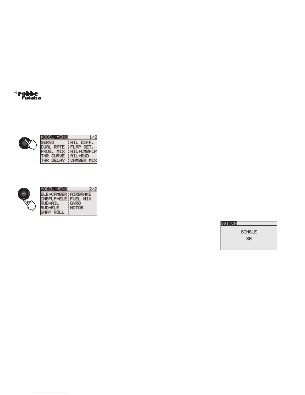
Because not all
functions needed
for Model-Menu can be displayed in just one screen, there is
a sub-menu in which the remaining functions can be selected.
Depending on the model type selected, there are the following
options:
• SERVO:
Servo monitor
• FLIGHT CONDITION: Select flight condition
• DUAL-RATE: Switched second control throw.
• PROG. MIX: Programmable Mixer
• THR CURVE: Set throttle curve
• THR DELAY: Throttle curve delay
• AIL. DIFF.: Aileron-Differential
• FLAP SET: Flap throw adjust
• AIL->CMBFLP: Aileron -> Flap Mixer
• AIL- BRAKE: Aileron -> Airbrake Mixer
• AIL->RUDDER: Aileron -> Rudder Mixer
• CAMBER MIX: Spoiler - Camber Flap Mixer
• ELE- BRAKE: Elevator- Spoiler Mixer
• CMBFLP-ELE: Camber flap. -> Elevator Mixer
• RUD->AIL: Rudder -> Aileron Mixer
• BUTTERFLY: Butterfly (Crow)
• TRIM MIX: Trim settings
• GYRO: Gyro settings
• V-TAIL: V-Tail settings
• AILVATOR: Ailvator settings
• WINGLET: Winglet-function
• MOTOR: Motor settings
• RUD->ELE: Rudder -> Elevator Mixer
• SNAP ROLL: Snap-Roll-Function
• AIRBRAKE: Spoiler/ airbrake mixer
• CAMBER FLAP: Landing flap Mixer
• MIXTURE: In flight mixture adjust
11.1 SERVO, SEE PAGE 22
11.2 FLIGHT CONDITION (GLIDER ONLY)
The T8FG Software has five different flight conditions or phase
settings available per model memory. For the different phases
of flight, the optimum settings for mixers and trim can be stored
and when needed, easily accessed by means of a switch. This
option allows you to program a glider with the perfect control
settings for the launch condition of flight.
Both ailerons and flaps are depressed so that the model has
maximum lift at launch. To maintain a stable trim, the eleva-
tor may be offset to mix a small amount of down elevator to
counteract any climbing tendency caused by the extra wing lift.
During the launch condition, this offset can be selected with a
switch or a defined control setting.
If several flight conditions are used in a single model memory,
the operational priority can be freely set as desired. The flight
condition can be copied. A condition delay time can be set for
each channel, so that when switching flight conditions, a “soft”
change is achieved without an abrupt change in model trim.
Using the “CAP TOUCH SENSOR“, select ‘CONDITION’ op-
tion in Model-Menu and confirm selection with “RTN”.
The Programming consists of the following steps:
• • SINGLE / LOGICAL Switch Functions
A single switch (Single) or a logically coupled (Logic) pair of
switches may be used to switch between flight conditions.
The following functions may be selected:
• AND: Series coupling of switches to activate the condition
E.g. “SA AND SB“ must be operated to activate the
function.
• OR: Parallel coupling of switches used to activate the
function E.g. “SA OR SB“ activates the function.
Model menu
34
2 x
1x