FUNCTION CHANGE
To be able to assign the functions to the correct channel, the
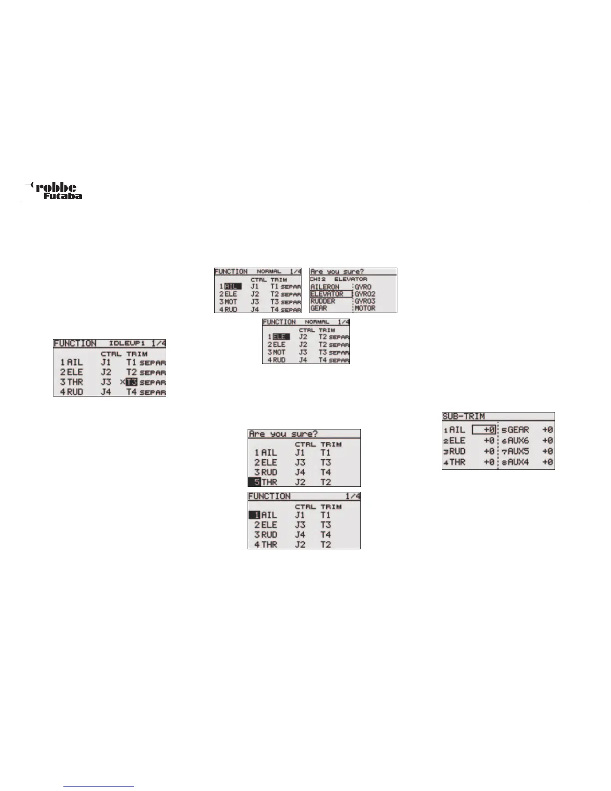
function can be moved or assigned to another servo output
channel.
To achieve this, select and highlight the function required. Then
the new function can be selected from the menu.
RECEIVER OUTPUT CHANGE
To be able to change the receiver servo output for example,
from channel 7 to channel 5, one can change the receiver
output, quickly and with no mechanical changes in the model.
10.7 SERVO CENTRE ADJUST/ SUB-TRIM
When installing servos in a model, it is always best to ensure
that the servo arm is in the neutral position when the transmit-
ter control and trim are also in the neutral position. If it is not
possible to achieve this or you find that the neutrals are incor-
rect on a model where the servos are already installed, the
sub-trim function can be used to set all servos on all channels
to the required exact neutral positions.
This option should only be used to make small neutral adjust-
ments; otherwise the servo throw will be limited in one direction
and asymmetrical.
The following procedure is recommended:
Firstly, adjust mechanically the servo arm and pushrod to
achieve the desired neutral position. The trim memory and set-
tings should be set to 0 %. Now use this menu to be able to set
the neutral precisely.
Note:
Set the servo direction before adjusting the sub-trim.
Select “SUB-TRIM” in the linkage menu using the “CAP
TOUCH SENSOR“ and confirm with “RTN”.
The servo positions are shown as a numerical value. Select
channel to be adjusted by scrolling the cursor to the required
channel. Scrolling the “CAP TOUCH SENSOR” to the required
value adjusts the sub trim value. The adjustment range lies
between –240 and +240 steps that approximate to +/- 20° of
servo travel. The initial value is set to 0 steps.
FX-20
Throttle Trim Lock (only Gliders and Helicopters)
So that the throttle trim does not get accidentally moved the
throttle trim levermay be locked so that it is inactive in all flight
conditions except „NORMAL“.
To be able to lock the throttle trim in Glider and Helicopter
model types, select IDLE UP 1-3 or AUTOROTATION. Then in
the FUNCTION menu, select THR trim (T1...4) and touch RTN
key for at least 1 second. An „X“ will appear in the throttle trim
field to indicate that the trim is locked and no longer active.
Note:
Switching off the throttle trimmer applies for each flight con-
dition!
Different trim settings per flight condition
COMB / SEPAR:
The function (Combined / Separate) is only displayed in the
helicopter and glider menus, because only these model types
operate with flight condition switching. See chapter 10.13 page
32.
It is a great advantage with helicopter models to be able to
separately change and store the trim settings when moving
from the static flight “hovering” to dynamic flight “aerobatics”.
VIRTUAL CHANNELS
These four channels, V-1 to V-4 can be configured as virtual
functions that do not have their own servo output channels and
share a “dual function” with another.
A virtual channel is a separate second control curve that works
with another control input. For example, Crow Braking function
which couples both aileron and camber flap servos/channels,
or the elevator function of a tail-less model that mixes aileron
and elevator channels together.
See the servo allocation table on pages 8 and 48 for the virtual
functions.
Linkage Menu
29