FX-20
Highlight the throttle cut position (POS) and set the servo po-
sition by scrolling the “CAP TOUCH SENSOR“ to the desired
%-age value of servo travel. The adjustment range lies bet-
ween 0 and 50%, the default value is 17%. Pressing the ‘RTN’-
key for at least 1 second will return to the default setting.
Operating the chosen switch will cut the motor when the throttle
stick is in the idle position.
Please take note of the following advice during the set-up:
• The throttle cut must be switched to OFF when starting the
motor.
• Set the percentage value so that the throttle butterfly is fully
closed, but the linkage has not hit its mechanical stop.
• If the throttle cut is ON when the transmitter is turned on, the
software will sound an alarm. Turn the throttle cut switch to
OFF to stop the alarm sounding.
• This alarm warns the pilot that the throttle is fully closed and
that the motor cannot be started
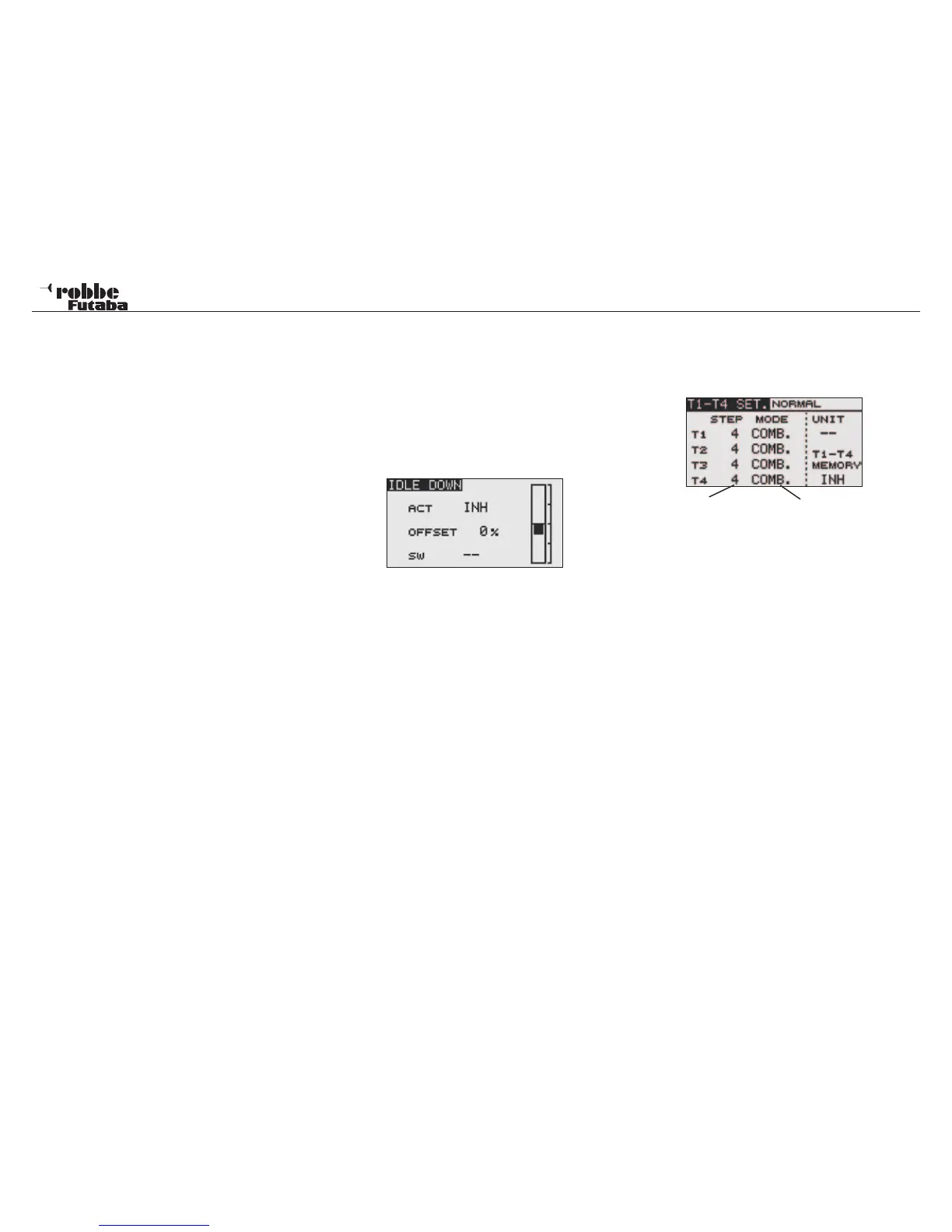
10.12 IDLE DOWN
The “IDLE DOWN” function allows you to reduce the motor
r.p.m. quickly to a reliable idle position by operating a switch
when the throttle stick is in the low throttle position, e.g. in the
landing approach condition.
The function only operates when the throttle stick is in the lower
range to avoid accidental “dead stick” landings happening.
Highlight “IDLE DOWN” with the “CAP TOUCH SENSOR“ in
the Linkage Menu and access the set-up screen below with
“RTN”:
Activate the function by highlighting ACT/INH line. Using the
“CAP TOUCH SENSOR“, change the setting from ‘INH’ to
‘ACT’ or “ON”, dependent on the switch position and press
‘RTN’-key.
• Using the “CAP TOUCH SENSOR“, highlight the ‘OFFSET’-
Position and set the required throttle position as a %-age
of the servo travel. The adjustment range is between 0 and
100%, the default setting is 0%. Pressing the ‘RTN’-key for
at least 1 second returns to factory pre-set default position.
Operating the chosen switch will move the throttle to the
desired motor rpm.
• After that, select a switch. Highlight the ‘--’ item and access
the switch set-up screen by pressing the ‘RTN’- key. Now
select the switch to operate Idle Down.
32
Linkage Menu
10.13 DIGITAL TRIM SETTINGS (T1-T4 SET)
Select (T1-T4 SET) in the Linkage Menu using the “CAP
TOUCH SENSOR“ and access the set-up screen below by
pressing “RTN”:
The settings can be either displayed as step amounts or per-
centage values for the digital trims (T1...T4). When the step
amounts should be displayed as percent then change the units
(UNIT) using the “CAP TOUCH SENSOR“ to percent values.
The Trim mode is set always to global (COMB) mode in “fixed
wing power model”, because no flight conditions are available
here.
The resolution of the trims can be adjusted from 1…200 using
the Step setting, so that the smallest inaccuracies may be trim-
med out. The pre-set Step-Value is 4, thereby giving a reso-
lution of -50 and +50 steps. With a Step-Value of 8, there is a
resolution of -25 to +25 steps.
The higher the value, then the resolution becomes “coarser”.
TRIM MEMORY OPERATION (T1-T4 SET)
If during the flight, the trims need to be adjusted, you are able
to store these settings using this function. Before turning off the
transmitter or changing the model memory, it is recommended
that you store the “new” trim settings. The model will be ideally
set up for the next flight and the trim buttons will be reset to a
neutral position of 0%.
Select (T1-T4 SET) in the Linkage Menu. Select T1-T4 Memory
„ACT“.
Trim Step Dis-
play
Selection global/separate
Only in Glider and Heli Modes