FX-20
11.13 CAMBER FLAP -> ELEVATOR MIXER
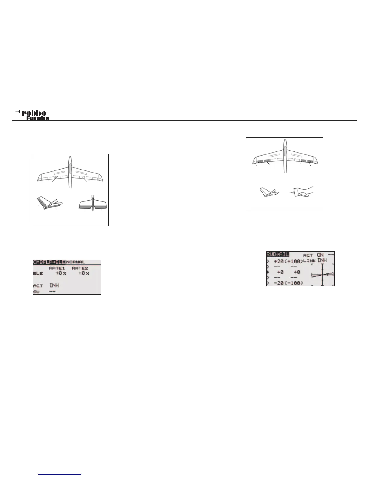
The CMBFLP-> ELE menu mixes elevator with the brake flaps/
spoliers. The elevators move in opposition to the spoilers to
increase the effectiveness of the flaps/spoilers.
The mix function can also be activated with a separate switch.
Highlight the “CMBFLP->ELE” option in the Model Menu using
the “CAP TOUCH SENSOR“ and confirm with “RTN”. The Dis-
play consists of one sub menu as follows:
Selecting from ACT/INH cell must first activate the mixer. High-
light this with the “CAP TOUCH SENSOR“ and activate using
“RTN”. This field will now indicate “ON” or “OFF”, dependent
upon the activation.
In the ‘SW’ cell, a switch can be assigned and its operating
direction defined in H/W SELECT menu. The pre-set condition
is always on when the display is set to ‘--’.
The setting of the throws for the elevator servos. Each servo’s
direction and throw as %-age can be set. The settings are
made in the typical manner. Highlight the item and confirm,
then adjust the %-age value using the scroll on the “CAP
TOUCH SENSOR“.
Finally, please note that the programming features and display
will differ according to model and wing type selected in the
Linkage Menu.
11.14 RUDDER -> AILERON MIXER
This menu func-
tion is used
when you want
to mix elevator
operation with
rudder opertion.
It is used to cor-
rect undesira-
ble tendencies
when rudder is
applied in rolling
maneuvers such
as, knife-edge and 3D flight. Also it is used in large models
and gliders to mix out unwanted roll interaction when applying
rudder.
Highlight the “RUD->AIL” option in the Model Menu using the
“CAP TOUCH SENSOR“ and confirm with “RTN”. The Display
consists of one sub menu, which is as follows:
The mixer must be first activated by selecting from ACT/INH
cell. Highlight this with the “CAP TOUCH SENSOR“ and acti-
vate using “RTN”. This field will now indicate “ON” or “OFF”,
dependent upon the activation. In the ‘SW’ cell, a switch can
be assigned and its operating direction defined in the usual
manner in H/W SELECT menu. The pre-set condition is always
on when the display is set to ‘--’.
Each aileron servo’s direction and throw as %-age can be set
for a given rudder throw. If it is required to mix the Flap servos
also, then the ‘LINK’ must be switched ON. Similarly, the flap
mixer that you wish to link to must also be turned ON, but no
further switch or control switch should be assigned otherwise
the “LINK“ Function will no longer work.
Model menu
41
Camber Flap
left (FLP)
Camber Flap
right (FLP2)
RUD
ELE
ELE2
ELE2
V-Tail Ailvator
Main
Aileron
(AIL2)
Chip ai-
leron
(AIL4)
Chip
aileron
(AIL3)
Main
Aileron
(AIL)
RUD
V-Tail Ailvator
ELE