FX-20
11.18 V-TAIL MIXER
(Only when V-Tail is selected in model type)
This Menu enables all the mix
functions to be programmed to
operate a V Tail airplane. The si-
gnals for rudder and elevator are
mixed so that two servos control
these functions. The throws for
elevator (controls move in the
same direction) and rudder (controls move in opposite direc-
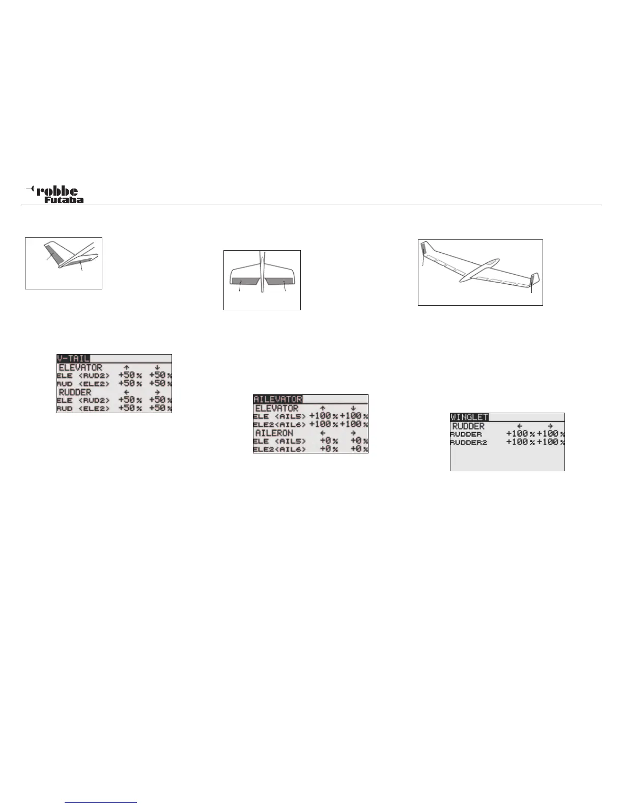
tion) can be individually programmed. The sketch shows the
servo assignment with a V-Tail.
After selecting V-TAIL as Tail type in the Linkage Menu, high-
light the “V-TAIL” Option in Model Menu and confirm with
“RTN”. The Display will be as follows:
For both control surfaces of a V-Tail, the throws and directions
are be entered as %age values in ELEVATOR and RUDDER
functions. The adjustment procedure is made in the typical
manner. After highlighting and confirming the %age field to be
adjusted, scrolling the “CAP TOUCH SENSOR“ to increase/
decrease the value and confirm with “RTN” to finish.
The pre-set value for all servos is 50%, touching the ‘RTN’-key
for at least 1 second will reset the values.
After programming the data, check thoroughly that the V-Tail
mixer works correctly with full and free movement of the con-
trols in the correct sense without hitting any mechanical stops.
11.19 AILEVATOR (ELEVATOR WITH AILERON) FUNC-
TION
(Only when Airplane + Ailvator Model Type is
selected in Linkage Menu)
This menu enables all the mix
functions to be adjusted to
operate twin elevator servos
as ailerons to improve the roll
response on a, typically, large
wingspan, powered model. Both
elevator surfaces can work in
the same sense as the ailerons
as well as normal elevators. The two elevator servos are each
connected to separate receiver outputs. On a V-Tail, this is
known as a Ruddervator as they serve the same purpose. The
sketch shows the servo assignment for a conventional tailplane
configuration.
Highlight the ‘AILVATOR’ Option in Model-Menu with the “CAP
TOUCH SENSOR“ and confirm with “RTN”. The Display will be
as follows:
The direction and throws (in %age) of the tailplane control
surfaces can be adjusted. The method has been extensively
described above. Following the highlighting and confirming the
appropriate fields, scroll the “CAP TOUCH SENSOR“ to adjust
the %age settings for the throws and confirm the settings with
“RTN”.
The pre-set values are set to 100% each; touching the ‘RTN’-
key for at least 1 second will reset the value.
After programming the data, check thoroughly that the Ailvator
mixer works correctly with full and free movement of the aileron
and elevator controls in the correct sense and without hitting
any mechanical stops.
11.20 WINGLET-RUDDER SETTINGS
(Only with Flying Wing Model type selection)
This Menu sets
all the mix func-
tions to control
the Wingtip Rud-
ders of a Flying
Wing model.
They function in
the same way as a conventional rudder mounted on the tail,
but are more effective because they do not operate within the
turbulent air-blast from the propeller.
The Induced drag of the wing is reduced and therefore the flight
performance is improved. This function is mainly used for flying
wing models fitted with winglets. The sketch shows the servo
assignment.
Highlight the ‘WINGLET’-Option in the Model-Menu using the
“CAP TOUCH SENSOR“ and confirm with “RTN”. The Display
is as follows:
The servo throw (%age) and direction can be adjusted for both
winglet rudders (RUDDER 1 and RUDDER 2”). The method is
described above. Following the highlighting and confirming the
appropriate fields, scroll the “CAP TOUCH SENSOR“ to adjust
the %age settings for the throws and confirm the settings with
“RTN”.
The pre-set values are set to 100% each; touching the ‘RTN’-
key for at least 1 second will reset the value.
Please note that this function only is available when the correct
Model Type (Flying Wing & Winglet) is selected in the Linkage
Menu.
Model menu
44
RUD/
ELE
ELE/
RUD
ELE
(AIL 5)
ELE 2
(AIL 6)
RUD 1
RUD 2