FX-20
Adjusting specific throttle conditions
The Tx Software has two pre-programmed throttle condition
already described in the Linkage Menu.
- THROTTLE CUT, Chapter. 10.11, S. 30
- IDLE DOWN, Chapter 10.12, S. 31
This menu programs the needle valve position for these two
throttle conditions. When activating such a function, the throttle
servo moves to a preset position, programmed by the throttle
condition selected. Simultaneously, the needle valve will be ad-
justed so that the mixture is optimized for the selected throttle
condition. The programming is made by setting the %age va-
lues using the usual programming method, i.e. highlight the
field and adjust the setting with the “CAP TOUCH SENSOR”.
12. LINKAGE MENU (HELICOPTER MODELS)
The functions of the Linkage Menu, which have already been
fully described previously, differ only with the addition of
swashplate and swashplate ring programming. Only the ad-
ditional Helicopter specific features are described here. The-
refore, please refer to pages 24-34 for a full description of the
rest of the functions of the Linkage Menu. The functions of the
Linkage Menu, which are already fully described already, are
to make the basic settings of a Model or Model Memory. The
individual data are stored under the Model Name in separate
memories.
Note:
When turning the Tx on, should the Display show: “WAR-
NING! IDLE UP1, 2 or 3” and the Tx alarm beeps, in such
a way the corresponding Switches must be switched to
“Normal“ or the “NO“ Field in the TRANSMIT? field se-
lected and confirmed by touching “RTN“.
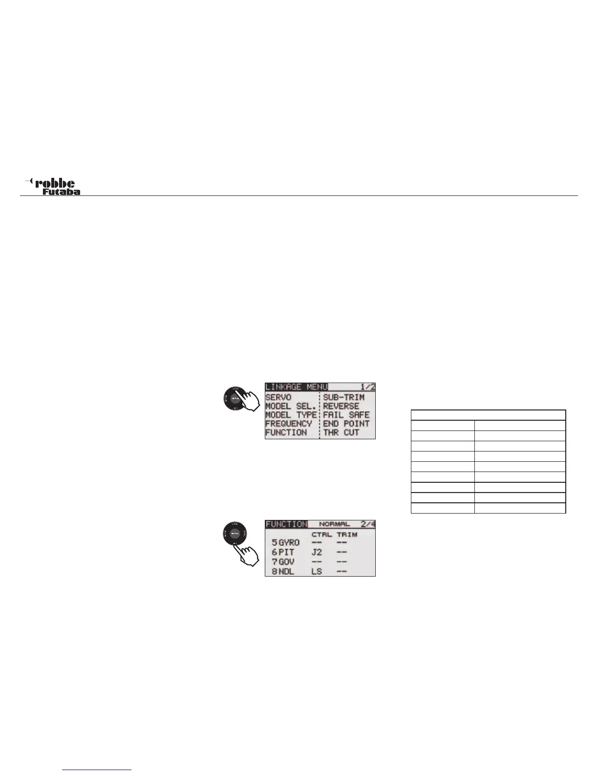
Highlight the Linkage Menu in HOME Display with the “CAP
TOUCH SENSOR“ and confirm selection with ‘RTN’. A sum-
mary of the Linkage Menu functions will now be displayed.
Since not all the functions of the Linkage Menu can be displa-
yed in a single Display, there is a second page that has the
remaining functions. This may be viewed by touching the S1
key to leaf between pages 1/2 and 2/2. Scrolling the “CAP
TOUCH SENSOR” to the last item on each page will automa-
tically leaf to the next page. The selection is made by scrolling
the “CAP TOUCH SENSOR“ in the required direction to select
the required function. The second page of the Linkage Menu is:
After activating the Helicopter Model Type, the following op-
tions may be selected:
SERVO: Servo throw bar chart see page 24
MODEL SEL: Model memory select see page 25
MODEL TYPE: Model type selection see page 26
FREQUENCY: Frequency- and Modulation select
page 28
FUNCTION: Control & Trim assignment and order
SUB-TRIM: Servo center fine adjustment see page 30
REVERSE: Servo direction reversing see page 31
FAIL SAFE: Fail Safe adjustment see page 31
END POINT: Servo maximum throw adjustment see
page 32
THR CUT: Motor cut function see page 32
SWASH RING: Throw Limit Display of swashplate
SWASH: Swashplate programming menu
T1-T4 SET: Adjust Trim steps and mode see page 32
WARNING: Warning of any active mixers see page 33
DATA RESET: Reset all Data to factory pre-sets see
page 33
RECEIVER OUTPUT ALLOCATION FOR HELICOPTER MO-
DELS
Note:
The receiver output channels 1-7 are the same for all Heli-
copter model types with the exception of H-4 and H-4X, which
uses channel 8 for “ELE 2“. All other swashplate types use
channel 8 for “NDL“.
48
Linkage menu helicopter
Model type Helicopter
Receive Output
1 AILeron Cyclic pitch
2 ELEvator Cyclic Pitch
3 THRottle
4 RUD/ Tail rotor
5 GYRO
6 Collective PITch
7 Rotor speed GOVernor
8 ELEevator 2 Cyclic Pitch/ NDL
2 x
1x